SM-131-006.pdf - 第174页
Device Name Chip Mounter Block Name Page No. Unit Name Revision Model Item GXH -1 Chapter 8 Com ponent Supply Section 1. Assembly of Feeder Positioning Section 1.1 Unit Attachment (1) Attach Section A (Fig. H1) and Secti…

0406-001 8-B
Device
Name
Chip Mounter
Block Name
Page No.
Unit Name
Revision
Model Item GXH-1
Chapter 8 Component Supply Section
1. Assembly of Feeder Positioning Section
1.1 Unit Attachment
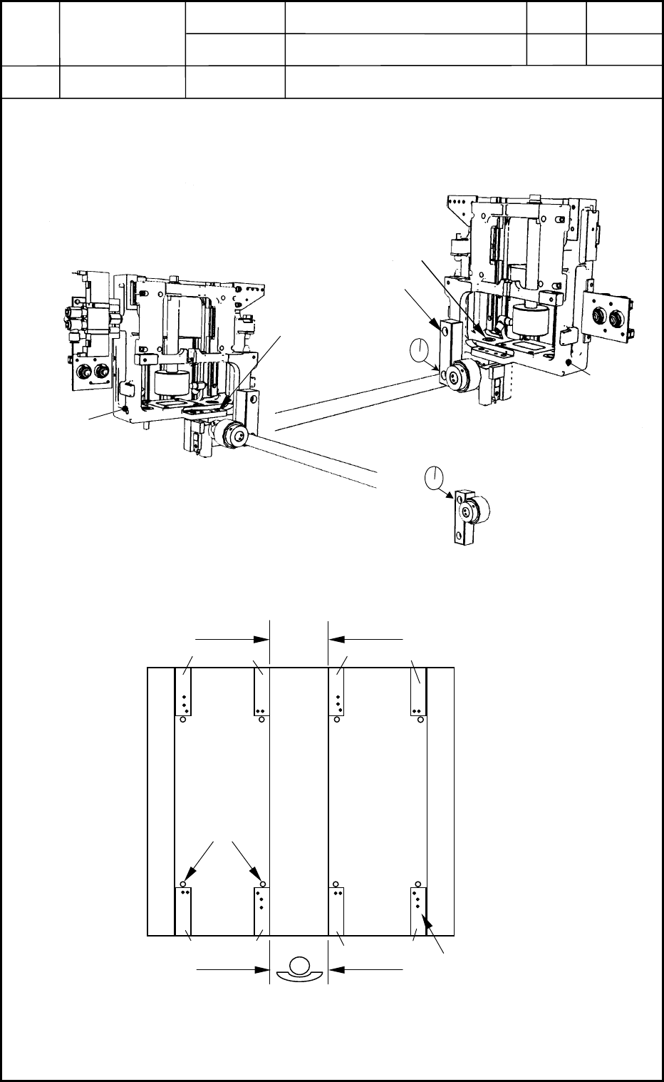
(1) Attach Section A (Fig. H1) and Section B (Fig. H2) to the main body.
0406-001
8-1
M
8
L2
0
Fig. H2 Positioning of Left Section
Section B (Left)
Fig. H1 Positioning of Right Section
(Ascending Position)
Section A (Right)
M10L40
M8L30
Fig. H3 Positioning of Right Section
(Descending Position)
Unit Base
Alignment
Center Stand
Positioning
Pins
Alignment
Alignment
Frame
B A B A
A B
Alignment
A B
Fig. H4 Unit Mounting Position
Device
Name
Chip Mounter
Block Name
Page No.
Unit Name
Revision
Model Item GXH-1
Chapter 8 Component Supply Section
1. Assembly of Feeder Positioning Section
(2) Both sides of the center stand on the frame should be regarded as reference ones.
Push the unit (X direction) on the center stand side against the stepped section.
Push the unit (Y direction) against the positioning pins on the frame and fix it securely.
(M10L40 SW, FW × 2)
As for the unit on the opposite side, push it (only Y direction) for temporary attachment.
(3) Temporarily attach the assembled gear sections to Unit Bases A and B.
(M8L20 SW, FW)
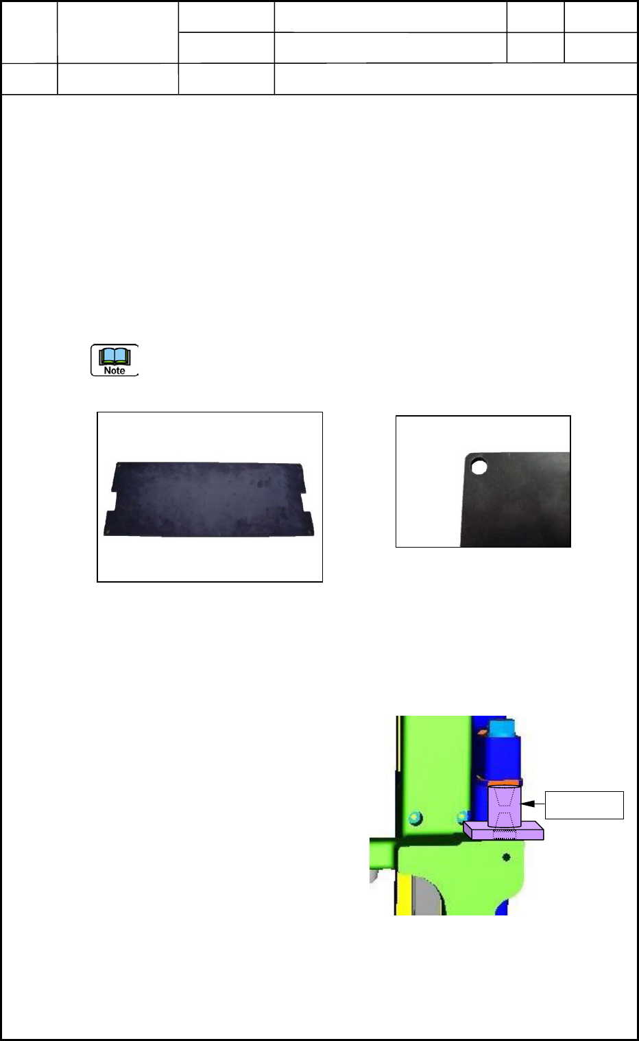
(4) Mount the unit positioning jig and adjust the X direction of the unit on the opposite side
of the center stand so that the jig can be detached and re-attached smoothly.
Adjust the X direction of the unit positioning jig at the center of the slot section shown
in Fig. H6. (As for the Y direction, push it against the pin.)
1.2 Pneumatic Piping
1.2.1 Adjustment
(1) Rotate the speed controller for elevation
one-and-a-half turns from the fully closed
condition and rotate the cushion two-and-
a-half turns backward from the fully
closed condition. After that, lock them.
(2) Attach the holding jig to the positioning
section and make the cylinder ascend.
Make sure that the mounting jig can be
pinched.
(3) Check the movement of the cylinder
through the manual operation of the valve.
Fig. H5 Unit Positioning Jig
Fig. H6 Slot Section of Unit Positioning Jig
Holding Jig
Fig. H7 Positioning of X Direction
0406-001
8-2