SM-131-006.pdf - 第145页
Device Name Chip Mounter Block Name Page No. Unit Name Revision Model Item GXH -1 Chapter 5 Head Section 7. MSB W hole Cleaning and Lubricat ion Procedures (30) Attach the Large and sm all diffusion pl ates of the head b…
Device
Name
Chip Mounter
Block Name
Page No.
Unit Name
Revision
Model Item GXH-1
Chapter 5 Head Section
7. MSB Whole Cleaning and Lubrication Procedures
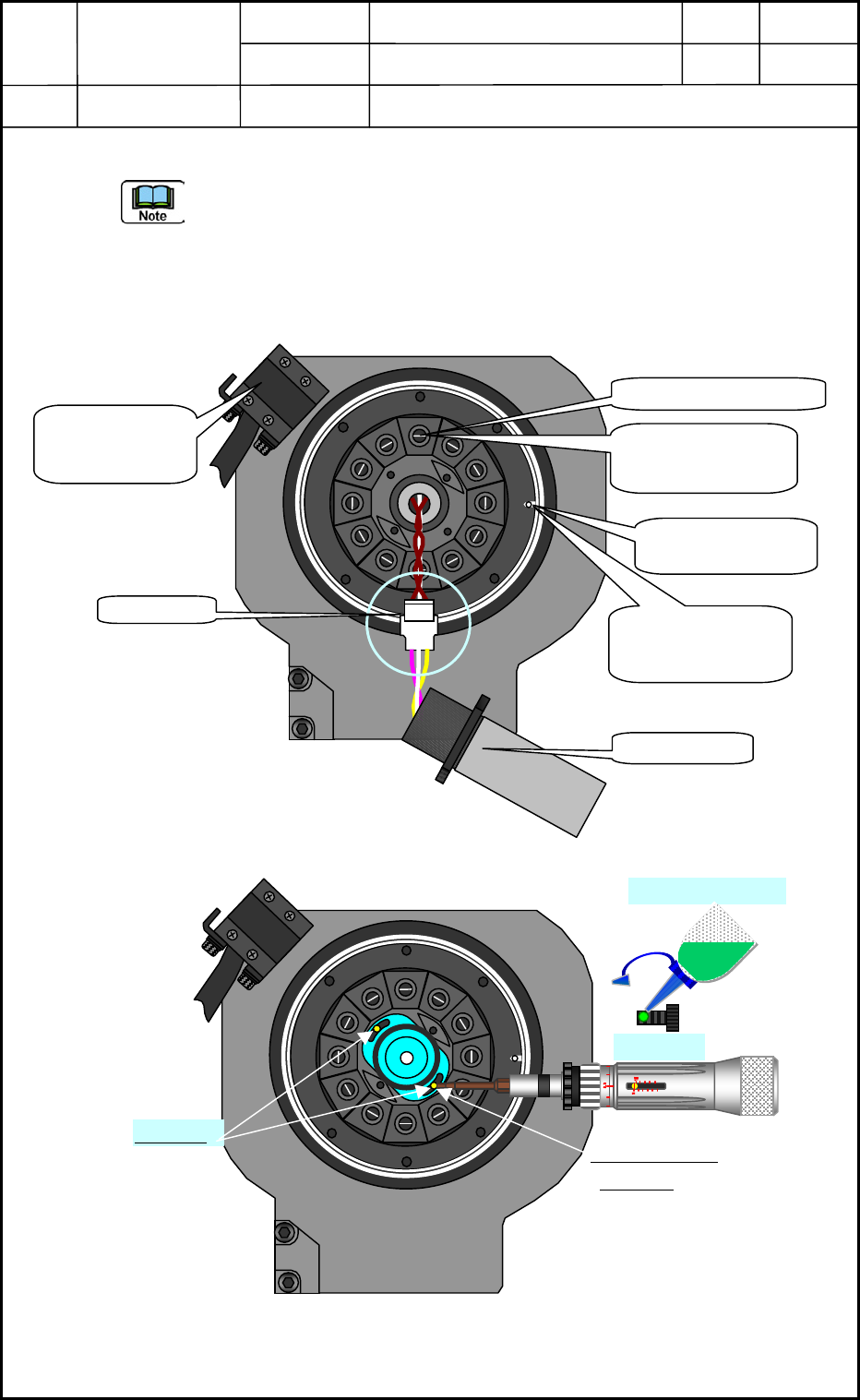
(29) Attach the linear measure sensor emission side.
- Attaching direction of the linear measure sensor: Turn the “white mark” <shown in Fig.
E78> to the light receiving side when the poison is the origin.
- Fixating position of the linear measure sensor: Fix it at the center of the slit shown in
Fig. E79.
- Replace the 2-M1.6×L4 bolts with new one and dispose of the old bolts.
- Apply the screw lock (Three Bond 1401B) to the M1.6×L4 slightly and tighten it with
a tightening torque (Torque Driver <See Fig. E79>) by 7.5 cNm (0.76 kg f cm).
Fig. E78
Fig. E79
M1.6×L4
M1.6×L4
Three Bond 1401B
Center Position
of the slit
View of Head Bottom Surface
Connector
White Mark
Positioning Pin
(Origin Position)
Linear Measure
Sensor Light
Receiving Side
No. 1 Nozzle Position
Direction: At 3:00
o’clock by clock
position
Direction: Just at
12:00 o’clock by
clock
p
osition
View of Head Bottom Surface
0605-001
5-43
Device
Name
Chip Mounter
Block Name
Page No.
Unit Name
Revision
Model Item GXH-1
Chapter 5 Head Section
7. MSB Whole Cleaning and Lubrication Procedures
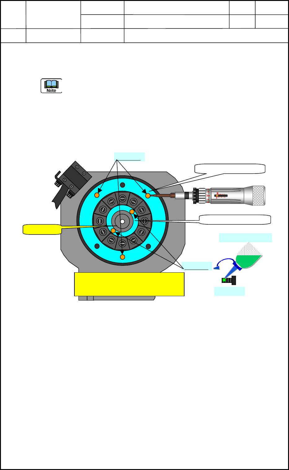
(30) Attach the Large and small diffusion plates of the head bottom surface shown in
Fig. E80.
(Large Diffusion Plate: 3-M1.6×L4 bolts, Small Diffusion Plate: 2-M1.6×L4 bolts)
- During this attaching operation, pay attention to the transparent area of the linear
measure sensor tip side section because the linear measure sensor protection cap is put
off at this time so, there is a possibility that the wrench or fingers touches that section.
Please take action to protect this section such as applying a wrench or covering this
section with plastic wrap.
- Replace the 5-M1.6×L4 bolts with new one and dispose of the old bolts.
- Apply the screw lock slightly (Three Bond 1401B) to the M1.6×L4 and tighten it with
a tightening torque (Torque Driver <See Fig. 80>) by 7.5 cNm (0.76 kg f cm).
Fig. E80
View of Head Bottom section
Caution!
Pay attention not to touch the linear
measure sensor tip section when
detaching the diffusion plates.
M1.6×L4
Large Diffusion Plate
Small Diffusion Plate
M1.6×L4
M1.6×L4
Three Bond 1401B
0605-001
5-44
Device
Name
Chip Mounter
Block Name
Page No.
Unit Name
Revision
Model Item GXH-1
Chapter 5 Head Section
7. MSB Whole Cleaning and Lubrication Procedures
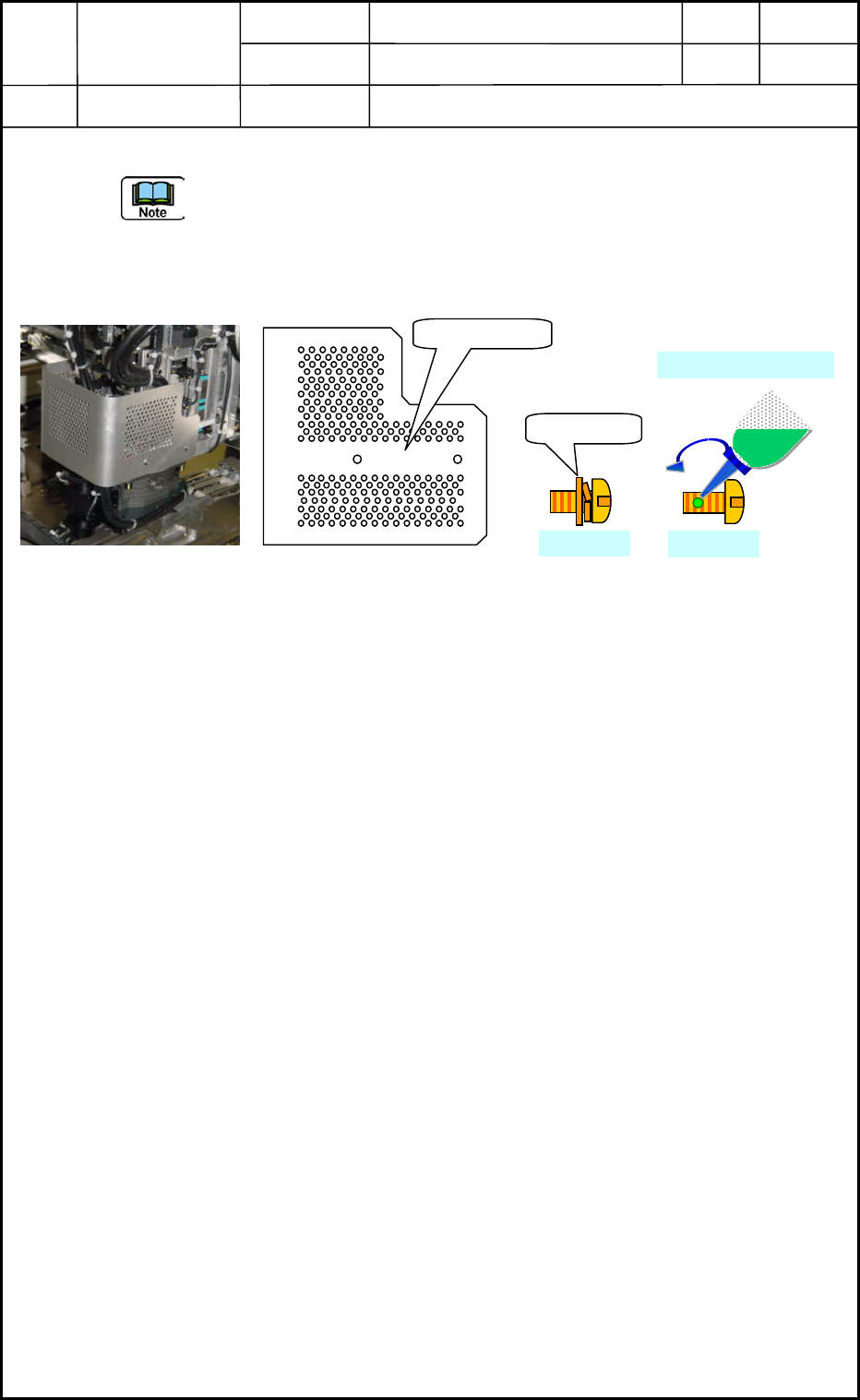
(31) Attach the head cover. <See Fig. E81>
- The head cover becomes common use in head No. 1 and 4, Head No. 2 and 3. Turn up
the cutting section in attaching the cover. (!Caution in upper/lower direction.)
- Fix the SUS4-M3×L6 truss screws of the old type with screw lock (Three Bond
1401B). However, there is no need for the new truss screws to apply screw lock.
Fig. E81 Fig. E82
(32) The operations of cleaning and lubrication of MSB (Miniature Stroke Bearing) are
completed. However, it is necessary to recheck around the head section and the machine
side if the grease has adhered on the diffusion plates, or some tools have been left
behind the machine. And attach the machine safety guard cover of the upper side of the
cart detached before this operation started.
Head Cover
New Type
M3×L6
M3×L6
Three Bond 1401B
0605-001
5-45