SM-131-006.pdf - 第209页
Device Name Chip Mounter Block Name Page No. Unit Name Revision Model Item GXH-1 Chapter 11 Recognition Section 2. Replacement of Co mponent Recognition Camera Fig. K17 Position of Component Recognition Camera Unit Attac…
Device
Name
Chip Mounter
Block Name
Page No.
Unit Name
Revision
Model ItemGXH-1
Chapter 11 Recognition Section
2. Replacement of Component Recognition Camera
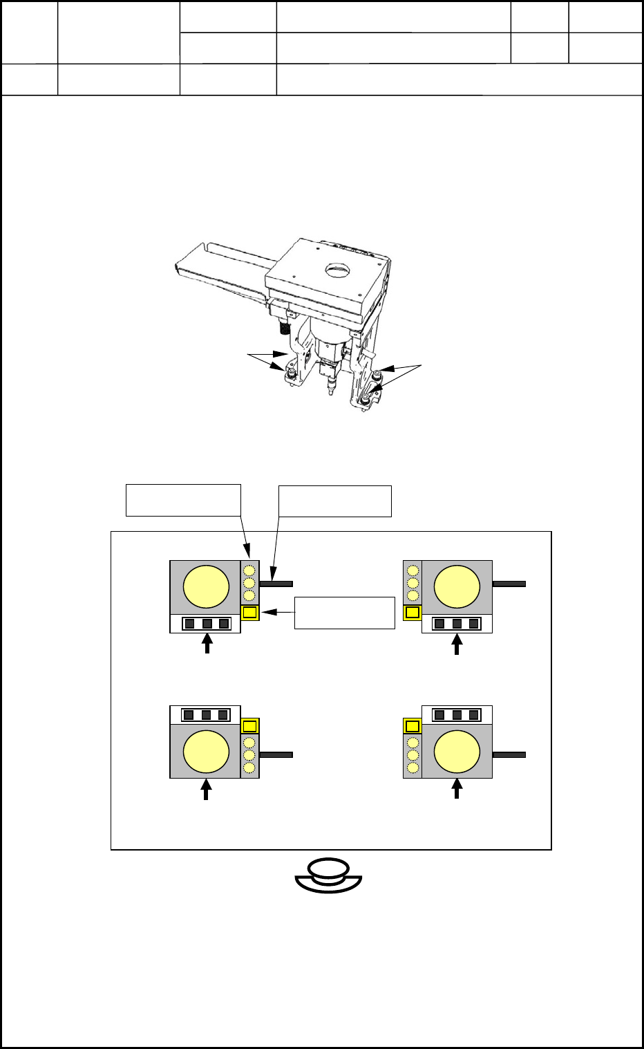
2.3 Attachment of Component Recognition Camera Unit
Attach the component recognition camera unit (Fig. K15) along the positioning pins on the
main body with four bolts (M8L30 SW, FW). (Figs. K16 and K17)
M8L30
M8L30
Fig. K15 Component Recognition Camera Unit
Front Side of Machine
Jig Holder
Ring Lighting
Coaxial Lighting
Direction of Camera Installation
(Name Plate Attachment Side)
Fig. K16 Direction of Component Recognition Camera Unit Attachment
Direction of Camera Installation
(Name Plate Attachment Side)
Direction of Camera Installation
(Name Plate Attachment Side)
Direction of Camera Installation
(Name Plate Attachment Side)
0406-001
11-7
Device
Name
Chip Mounter
Block Name
Page No.
Unit Name
Revision
Model ItemGXH-1
Chapter 11 Recognition Section
2. Replacement of Component Recognition Camera
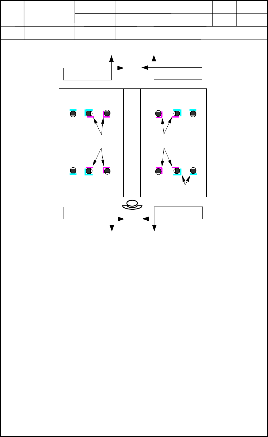
Fig. K17 Position of Component Recognition Camera Unit Attachment
Nozzle Stocker Positions
Component Recognition
Camera Positions
Pushing
Pushing
Pushing
Pushing
Component Recognition
Camera Positions
0406-001
11-8

Chapter 12
Control Section
This chapter describes how to replace the control section.
• Replacement of CPU1
• Replacement of HDD
• Replacement of CPU2
• Replacement of Recognition Box
0406-001 12-A