SM-131-006.pdf - 第122页
Device Name Chip Mounter Block Name Page No. Unit Name Revision Model Item GXH -1 Chapter 5 Head Section 7. MSB W hole Cleaning and Lubricat ion Procedures 7.1 Purpose The purpose of this material is to prev en t and imp…
Device
Name
Chip Mounter
Block Name
Page No.
Unit Name
Revision
Model ItemGXH-1
Chapter 5 Head Section
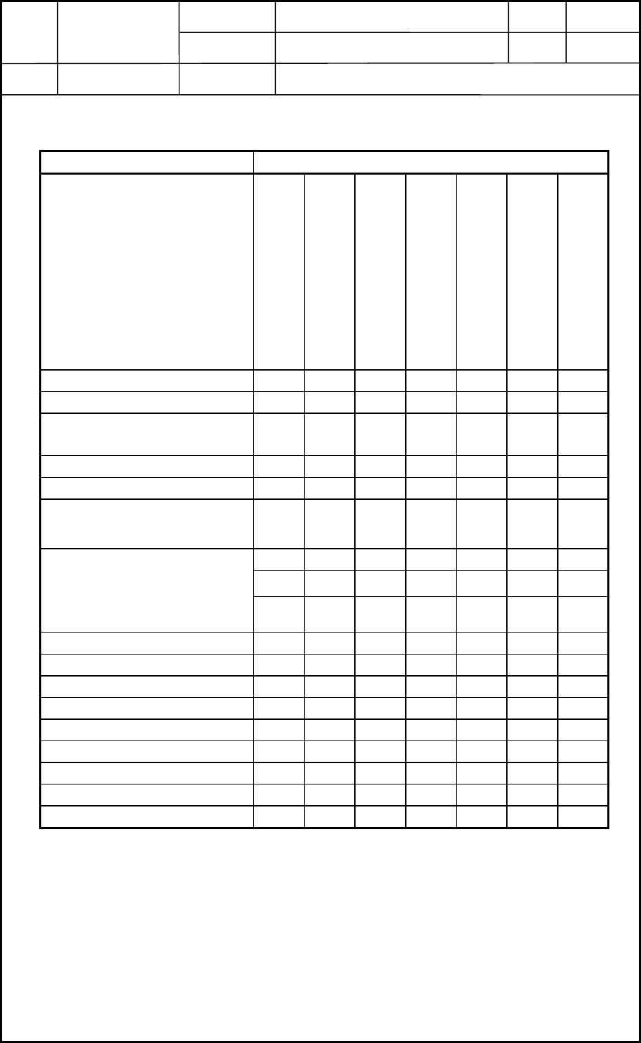
6. Adjustment of Offsets
6.1 Order of Offset Adjustments
Order of Offset Adjustments Procedure for Replacement
Delivery, Transfer, and
Installation
Head Unit
Nozzle Assembly
PEC Recognition Camera
Linear Head Scale
X/Y Motor
Component Recognition
Camera
Nozzle Up/Down Offset 1 1 1 --- --- 2 ---
Feeder (A) Offset L: Up/Down 2 2 2 --- --- 3 ---
Feeder (B) Offset (Manual
Alignment of Pickup Position)
10 11 10 4 8 11 ---
Nozzle Position Offset 8 9 8 --- 6 9 ---
Nozzle Level Offset 9 10 9 --- 7 10 ---
PEC Recognition Camera & Beam
Offset
5 5 --- 1 2 5 ---
6652361
--- --- --- --- --- --- ---
Component Recognition Camera
Offset Teaching
Magnification Teaching
Lighting Teaching
--- --- --- --- --- --- ---
Head Rotational Axis Offset --- 7 6 --- 4 7 2
Head Center/Mark Position 7 8 73583
Fly Recognition Camera Offset --- --- --- --- --- --- ---
Feeder Base Feeder (A) Offset --- --- --- --- --- --- ---
Master Nozzle Level Offset 3 3 3 --- --- 4 ---
NL-Axis Origin Offset 4 4 4 --- --- --- ---
Table Offset --- --- --- --- --- --- ---
Y-Axis Origin Offset --- --- --- --- 1 1 ---
Nozzle Stocker Offsets --- --- --- --- --- --- ---
0406-001
5-20
Device
Name
Chip Mounter
Block Name
Page No.
Unit Name
Revision
Model Item GXH-1
Chapter 5 Head Section
7. MSB Whole Cleaning and Lubrication Procedures
7.1 Purpose
The purpose of this material is to prevent and improve defects for the nozzle up/down
movement by soils of the nozzle shaft on the head section in daily product operations.
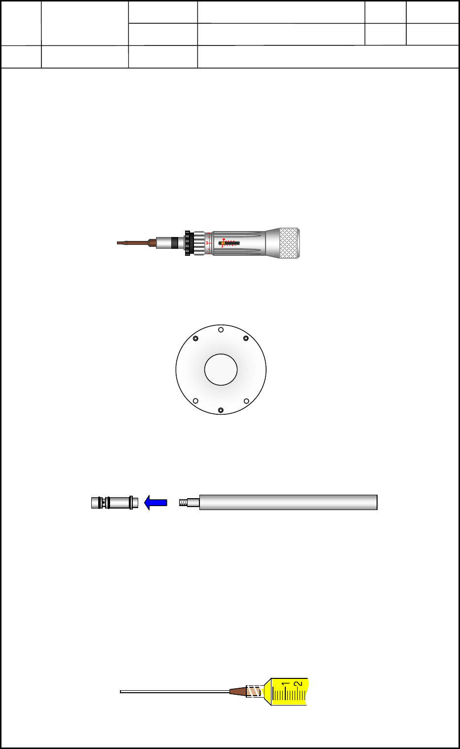
7.2 Required tools
Machine tools and Jigs
• An Allen Wrench (Straight type: recommendations: TONE and BONDUS)
• A Torque Driver (M1.6×L3 including a bit for hexagon head bolt)
7.5cNm (Select the one that setting by 0.76kg f cm is possible.)
• Head section attaching Jig (A bottom lid for preventing the nozzle shaft jumping out)
• Nozzle holder inserting Jig
• Standard plus driver
• Linear Measure Sensor protection cap
• Reference Tool: Bamboo Skewer (Use for applying grease on the retainer section)
• Ultrasonic Cleaner (use for cleaning of nozzle shaft)
• Jig for exclusive use in Nozzle Shaft Cleaning (See Fig. 63 in this material page 5-34)
• Lubrication Jig SS-10LZ (Standard Accessory) and Lubrication Nozzle (Type: No.19)
0605-001
5-21
Fig. E42 JG-0245
Fig. E43 JG-0197
Nozzle Holder
Nozzle holder inserting Jig
Fig. E44 JG-0231
Fig. E45

Device
Name
Chip Mounter
Block Name
Page No.
Unit Name
Revision
Model Item GXH-1
Chapter 5 Head Section
7. MSB Whole Cleaning and Lubrication Procedures
Others (including consumption articles)
• Grease (DAPHNE EPONEX GREASE No.1)
• Screw Lock (Three Bond 1401B) <Slightly use it on the top block section and fixing
bolts.>
• New Bolts (M1.6×L3) for replacement in attaching the top block section
(Preparation: Up to the number of cleaning.)
• New Bolts (M1.6×L4) for replacement in attaching the diffusion plates (large ,small),
linear measure sensor section and the lower rotor section.
• P19 size (12P×2) for use O-ring nozzle holder section…Whole replacement: once 2 years
• P21 size (12P) for use O-ring MSB outer cover parts… Whole replacement: once 2 years
• V-packing MSB outer cover and nozzle shaft holder section (12P for each place)
… Whole replacement: once 2 years
• Rags for cleaning operation and covering the floor of the working place.
• Kerosene for cleaning of nozzle shaft
0605-001
5-22
Fig. E46