SM-131-006.pdf - 第140页
Device Name Chip Mounter Block Name Page No. Unit Name Revision Model Item GXH -1 Chapter 5 Head Section 7. MSB W hole Cleaning and Lubricat ion Procedures (23) Clean up the DD motor inside (upper rotor) <in Fig. E71&…
Device
Name
Chip Mounter
Block Name
Page No.
Unit Name
Revision
Model Item GXH-1
Chapter 5 Head Section
7. MSB Whole Cleaning and Lubrication Procedures
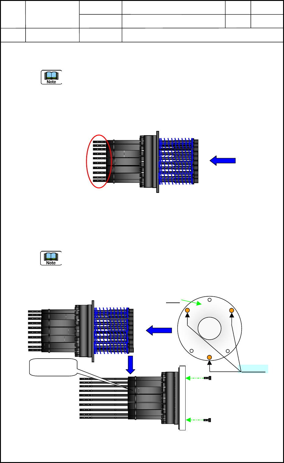
(21) Insert the nozzle shaft slowly to the lower rotor outer cover of the head section after
checking the inserting direction.
- Return them to the former nozzle shaft No. positions properly.
- When inserting operation, do not force the nozzle shaft to insert, otherwise it may
cause damages and get disengaged V-packing.
- Wipe off the grease with a rag if the extra grease left on the pointed section of the
nozzle shaft in the following Fig. E69 (Circled) after inserting the nozzle shaft.
Fig. E69
(22) Attach the head section attaching jig (a lid for preventing jumping out the nozzle shaft)
to the nozzle shaft Assy with using the screw hole of the large diffusion plate attaching
tap like the Fig. E70 below.
Hold the head section attaching jig securely, otherwise the bolt will slant by M1.6×L4
spring. If tightening it with slanted bolt, the screw thread may be damaged. And, do not
add the force to the shaft section. We recommend that the operators work in pairs as
long as this operation
to perform holding and tightening work together.
Fig. E70
0605-001
5-38
Mark
Nozzle
Shaft Assy
No.1
M1.6×L4
Device
Name
Chip Mounter
Block Name
Page No.
Unit Name
Revision
Model Item GXH-1
Chapter 5 Head Section
7. MSB Whole Cleaning and Lubrication Procedures
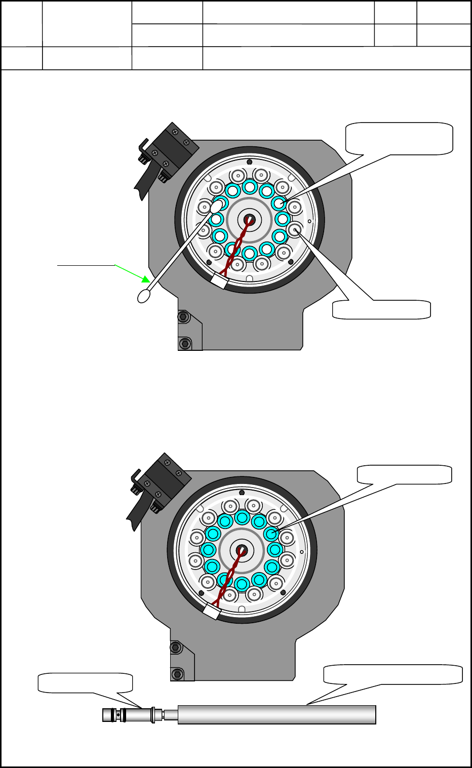
(23) Clean up the DD motor inside (upper rotor) <in Fig. E71> with a cotton swab dipped on
alcohol.
Fig. E71
(24) Return the 12-nozzle holders in the DD motor section (upper rotor) with a nozzle holder
inserting jig.
Fig. E72
0605-001
5-39
Cotton Swab
View of Head Bottom Surface
Vacuum Valve
Cleaning of nozzle
holder section
Nozzle Holder Inserting Jig
Nozzle Holder
Nozzle Holder
View of Head Bottom Surface
Device
Name
Chip Mounter
Block Name
Page No.
Unit Name
Revision
Model Item GXH-1
Chapter 5 Head Section
7. MSB Whole Cleaning and Lubrication Procedures
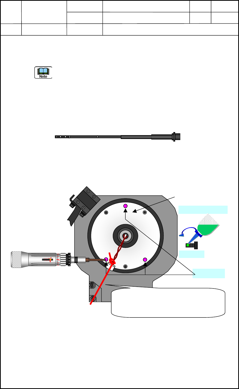
(25) Insert the nozzle shaft assy tenderly and vertically to the DD motor (upper rotor) from
the bottom side. In this case, not to give road on the nozzle shaft, after that fix it with
M1.6×L4 bolts at the section shown in Fig. E74.
- Replace 3-M1.6×L4 bolts with the new one. Please dispose of the old bolts.
- Before inserting the nozzle shaft assy, tie the linear sensor connector with a string.
And insert the nozzle shaft assy pulling the string tenderly from the center. This
procedure will make the inserting operation easily.<See Fig. E74>
- If the nozzle shaft assy is forced to insert, the V-packing of the nozzle holder inside
may be damaged.
- wipe off extra grease with a rag if it has adhered on the nozzle shaft upper section (See
Fig. E73).
Fig. E73
- Apply the screw lock (Three Bond 1401B) slightly to the M1.6×L3 and tighten it with
a tightening torque (Torque Driver) by 7.5 cNm (0.76 kg f cm).
Fig. E74
0605-001
5-40
No.1 ノズル
No.1
No.1 Nozzle Position
Three Bond 1401B
M1.6×L4
M1.6×L4
View of Head Bottom Surface
Pass the string through the nozzle shaft
assy inside. Insert the Assy pulling this
string tenderly. This procedure prevents
the nozzle shaft gets tangled up.