SM-131-006.pdf - 第61页
Device Name Chip Mounter Block Name Page No. Unit Name Revision Model Item GXH-1 • Measuring Position of Feeder Base (X/Y Coordinates) Measure the three feeders (F125, F101, and F149) on each feeder base. Shown in Table …
Device
Name
Chip Mounter
Block Name
Page No.
Unit Name
Revision
Model ItemGXH-1
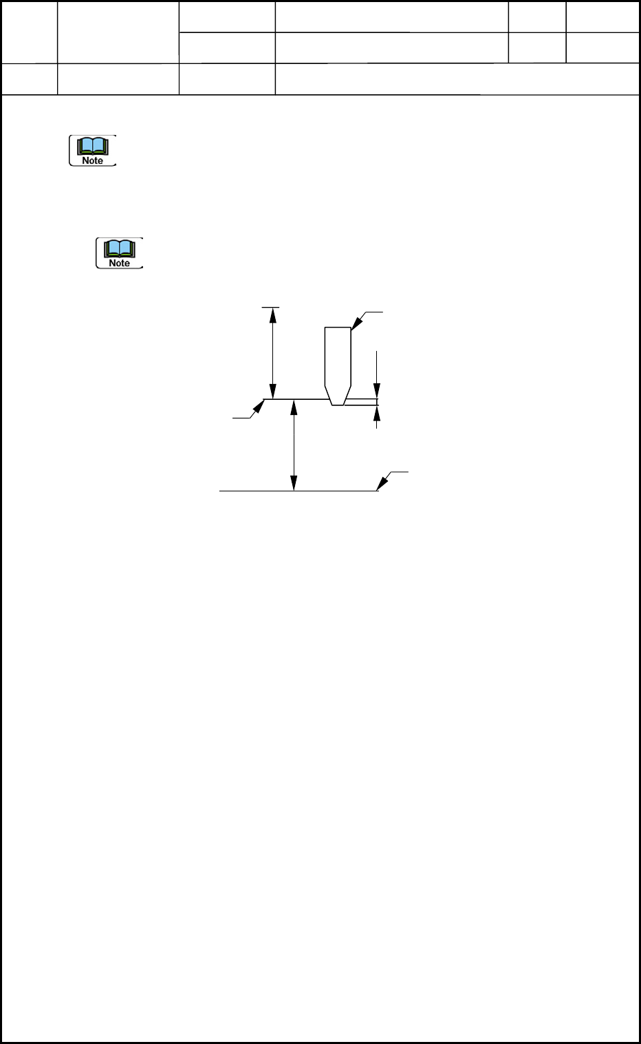
2.2.2 Feeder (A) Offset (L: Up and Down)
It is required to release the [STAGE READY] switches because this maintenance
work must be performed with the doors being opened.
• Measurement and Entry of Offsets (compared with both ends of each feeder) and
Automatic Calculation (Expected Function) of Feeder Offsets
The head level offsets are also considered for the pickup height but not for the
inching (manual alignment) operation.
Example of Data Entry : 0.21 mm, assuming that the nozzle is located below the
reference plane and a plus value must be entered.
Regarding the head level offset as a feeder offset for which the
head level offset (L2 = -0.21), Head Level Offset L1 equals to
"-0.1 mm".
Feeder (A) Offset
L2 - L1 = -0.21 - (-0.1) = -0.11 mm
Heads
2. Installation Offset
1-7
Design Value of
Stroke
Fig. A7 Measurement of Feeder Offset
32
Master Nozzle
Pickup Upper Plane
Reference
0.21
L2
104
Upper Surface of
Feeder Base
Unit : mm
0403-001
Device
Name
Chip Mounter
Block Name
Page No.
Unit Name
Revision
Model ItemGXH-1
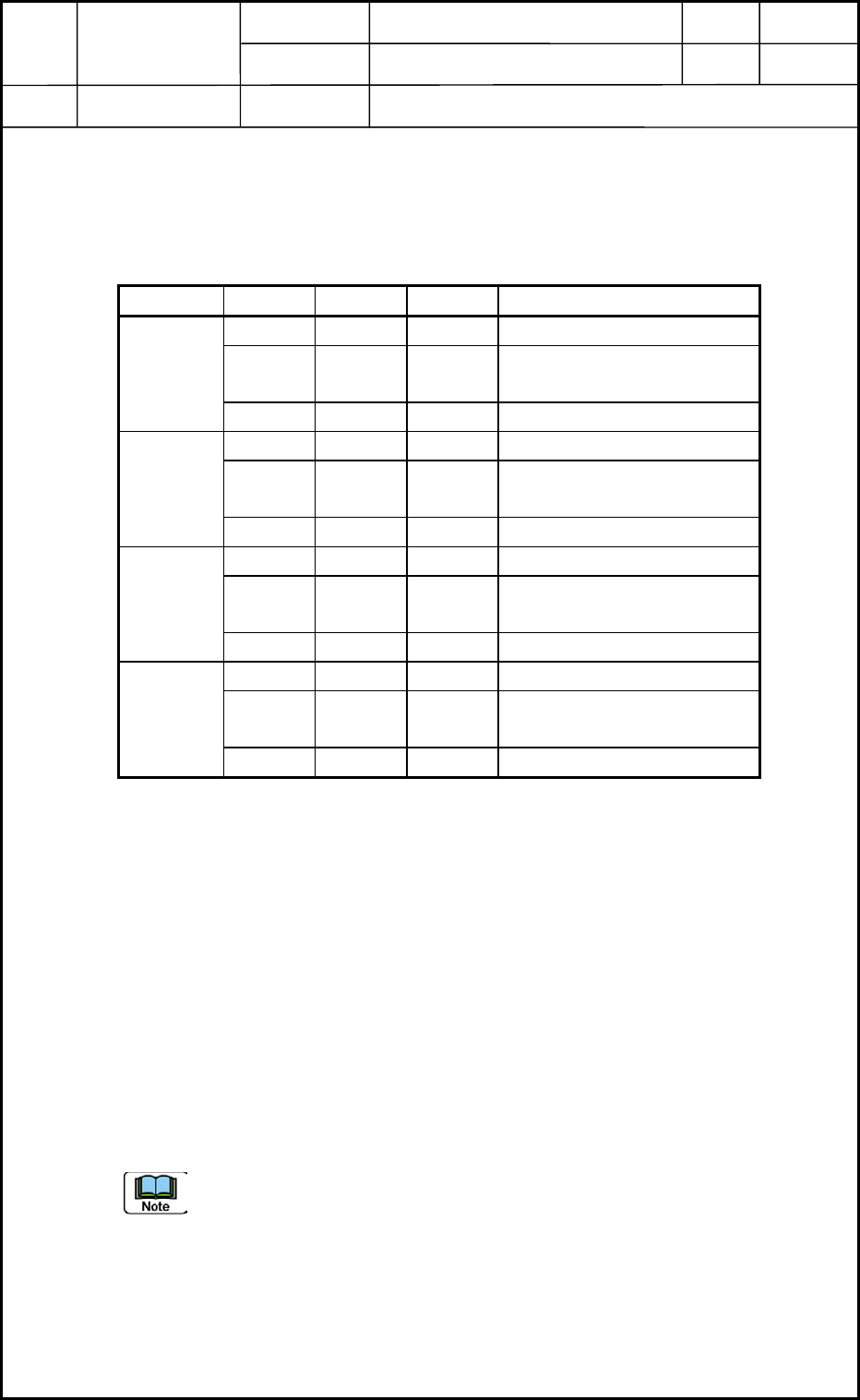
• Measuring Position of Feeder Base (X/Y Coordinates)
Measure the three feeders (F125, F101, and F149) on each feeder base.
Shown in Table A1 are the distances between the origin and F125, between F125 and F101,
and between F125 and F149.
Table A1
X (mm) Y (mm)
F101 +250 - Manual Alignment from F125
F125 +5.75 +10 Manual Alignment
from Origin Position
Head 1
F149 -250 - Manual Alignment from F125
F201 -250 - Manual Alignment from F225
F225 5.75 -10 Manual Alignment
from Origin Position
Head 2
F249 +250 - Manual Alignment from F225
F301 +250 - Manual Alignment from F325
F325 +5.75 +10 Manual Alignment
from Origin Position
Head 3
F349 250 - Manual Alignment from F325
F401 -250 - Manual Alignment from F425
F425 5.75 -10 Manual Alignment
from Origin Position
Head 4
F449 +250 - Manual Alignment from F425
• Entry of Offset Data
Operation Sequence: [SUPV] Button → [EDIT] Button → [SYSTEM] Button → [EDIT]
Button entitled "Machine System" → "Device Offset" Tab Sheet → "Feeder-A" Tab Sheet
Enter parameters for "L (Height)" in the "Feeder Base 1", "Feeder Base 2", "Feeder Base
3", and "Feeder Base 4" tab sheets. After the entry, save the changes.
Example of Data Entry:
Measured Data for F101 : Items in Offsets F101 throuth F110
Average of Measured Data for F101 and F125 : Items in Offsets F111 through F120
Measured Data for F125 : Items in Offsets F121 through F130
Average of Measured Data for F125 and F149 : Items in Offsets F131 through F140
Measured Data for F149 : Items in Offsets F141 through F150
The items must be divided into every three items and the data must be entered
individually.
Heads
2. Installation Offset
1-8
0406-002
Device
Name
Chip Mounter
Block Name
Page No.
Unit Name
Revision
Model ItemGXH-1
2.3 Automatic Offset
2.3.1 PEC Recognition Camera and Beam Offsets
• Confirmatory Operation of Offset Values
(1) Select one of the [1], [2], [3], and [4] buttons in the "camera/beam select" group box of
the "RECOG CAMERA & BEAM OFFSET" window. (Operation Sequence: [MAINT.]
Button → [TEACHING] Button → [OTHERS] Button → [PEC RECOG & BM OFST]
Button)
Select the [Not use] button in the "Glass jig" group box.
Select the [Teach Start] button and press the [START] button to start the teaching
operation.
When there is not a big difference in the values between "Crnt" and "Adj", it is
not required to perform this teaching operation.
Otherwise, the teaching operation must be performed, using the glass jig PCB.
(2) Follow the same procedure for "[1] through [4]" in the "camera/beam select" group box.
Required Jig : Glass Jig PCB (460 × 250 mm)
No support pin is required.
• Clamping Procedure of Glass Jig PCB
(1) Zero the conveyor width.
Open the "PROD. CHG." window by pressing the [PROD. CHG.] button
and zero the L conveyor, the conveyor, and the R conveyor.
(2) Change the conveyor width.
Open the "ADJUST" window and select the [Stage #1] or the [Stage #2]
button. (Operation Sequence: [OPERATOR] Button → [MAINT.] Button
→ [DVC CHECK] Button → [ADJUST] Button)
Set "BackUp Base" in the "Opn mode" text box in the P.C.B. transfer"
group box.
Enter "250.5" for "Wd" and "114.75" for "Ofst" in relation with each item
"stg#1", "Center", "Stg#2" in the "Suiting of width of conveyor (Start)"
group box.
When each button in the "Suiting of width of conveyor (Start)" group box
is selected and the [START] button is pressed, the corresponding
conveyor width is changed.
Enter "250" in the "Tgt Wd" text box and "0.8" in the
"Clearance" text box, "115" in the "Base Pos" text box in the
"Cnvr Wd" group box of the "PRODUCT CHANGE" window.
Move the L conveyor, the conveyor, and the R Conveyor to the
target positions.
Example : Selecting [L Cnvr] Button → Selecting [Desig
Width] Button → Pressing [START] Button
Heads
2. Installation Offset
1-9
0403-001