SM-131-006.pdf - 第147页
Device Name Chip Mounter Block Name Page No. Unit Name Revision Model Item GXH -1 Chapter 5 Head Section 7. MSB W hole Cleaning and Lubricat ion Procedures (33) Turn on the air, after that turn on the machine and start u…
Device
Name
Chip Mounter
Block Name
Page No.
Unit Name
Revision
Model Item GXH-1
Chapter 5 Head Section
7. MSB Whole Cleaning and Lubrication Procedures
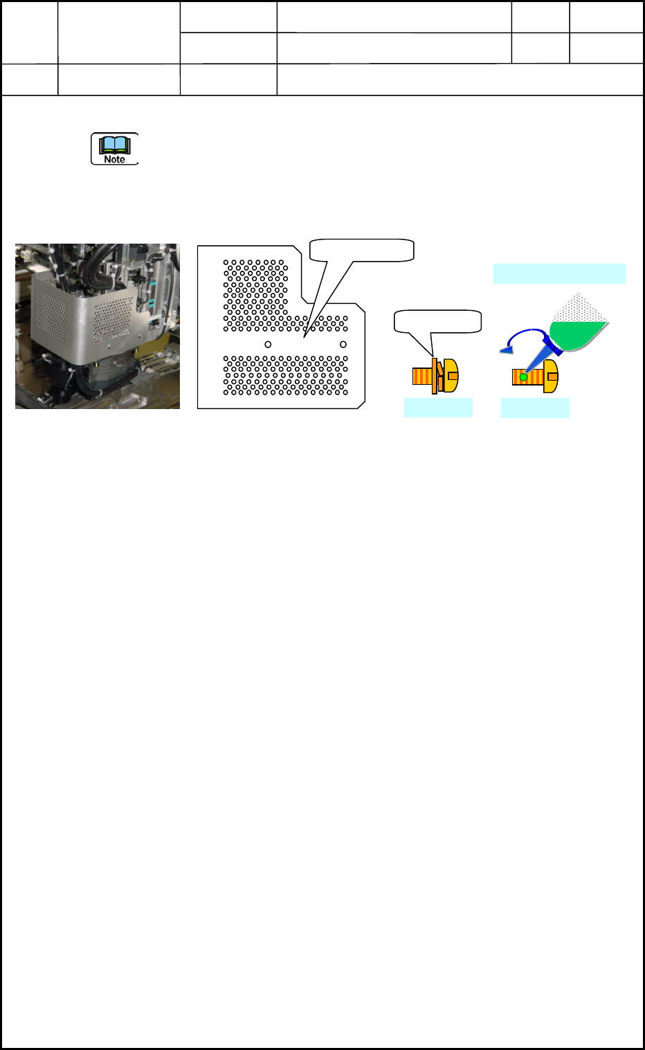
(31) Attach the head cover. <See Fig. E81>
- The head cover becomes common use in head No. 1 and 4, Head No. 2 and 3. Turn up
the cutting section in attaching the cover. (!Caution in upper/lower direction.)
- Fix the SUS4-M3×L6 truss screws of the old type with screw lock (Three Bond
1401B). However, there is no need for the new truss screws to apply screw lock.
Fig. E81 Fig. E82
(32) The operations of cleaning and lubrication of MSB (Miniature Stroke Bearing) are
completed. However, it is necessary to recheck around the head section and the machine
side if the grease has adhered on the diffusion plates, or some tools have been left
behind the machine. And attach the machine safety guard cover of the upper side of the
cart detached before this operation started.
Head Cover
New Type
M3×L6
M3×L6
Three Bond 1401B
0605-001
5-45
Device
Name
Chip Mounter
Block Name
Page No.
Unit Name
Revision
Model Item GXH-1
Chapter 5 Head Section
7. MSB Whole Cleaning and Lubrication Procedures
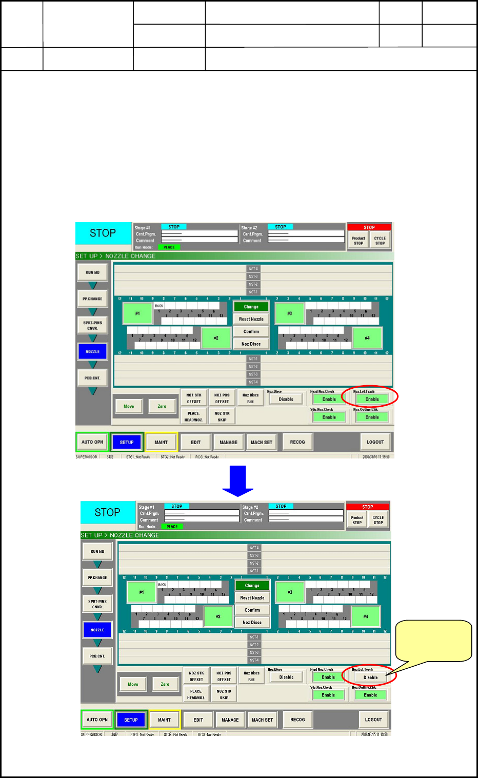
(33) Turn on the air, after that turn on the machine and start up the main body.
• After the main body starts up, perform all zeroing operation.
• Open the [SETUP] => [NOZZLE] tab sheet below <Fig. E83> and set the “Disable”
for the nozzle level teaching. If the “Enable” is set, the machine gets offset operation
automatically when taking the nozzle and the data for “before lubrication” will be
changed. Therefore, the “after lubrication” data can not be compared with the “before
lubrication” ’s one any more.
Fig. E83
Change the
setting to
“Disable”.
0605-001
5-46
Device
Name
Chip Mounter
Block Name
Page No.
Unit Name
Revision
Model Item GXH-1
Chapter 5 Head Section
7. MSB Whole Cleaning and Lubrication Procedures
• At the [SETUP] => [NOZZLE] tab sheet, perform the nozzle change. The heads
cleaned this time will go taking the nozzles used before in the nozzle level teaching
operation. In this case, the order should be the same as before. (No special operation
is required to make the same condition as before.)
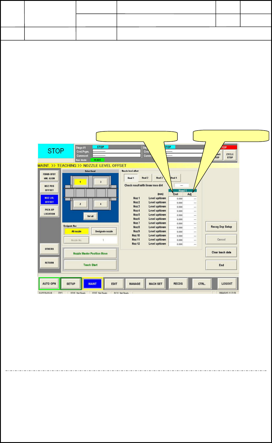
• Perform the nozzle level offset teaching against the heads cleaned and supplied this
time.
• Compare the difference of data between the “after lubrication” and the “before
lubrication” with the teaching result and the difference should be ±0.01mm against
the all nozzles.<Fig. E84>
Fig. E84
• When the difference is within ±0.01mm, perform teaching operation for others:
nozzle position offset.
• After teaching operation, reset the “Disable” to the “Enable”. Then, this all operations
are completed.
<In case of out of range>
If the difference is not within ±0.01mm, recheck the linear measure sensor attaching direction
and position, soil, damage or etc. otherwise, the bottom rotor section and linear measure
sensor attaching section have trashes and soils or the screw lock (Three Bond 1401B) remains.
Nevertheless, when the problem can not be improved, contact nearest service personnel in our
company.
Before Lubrication data
After Lubrication data
0605-001
5-47