SM-131-006.pdf - 第183页
Device Name Chip Mounter Block Name Page No. Unit Name Revision Model Item GXH-1 Chapter 8 Component Supply 0406-001 8-10
Device
Name
Chip Mounter
Block Name
Page No.
Unit Name
Revision
Model ItemGXH-1
Chapter 8 Component Supply
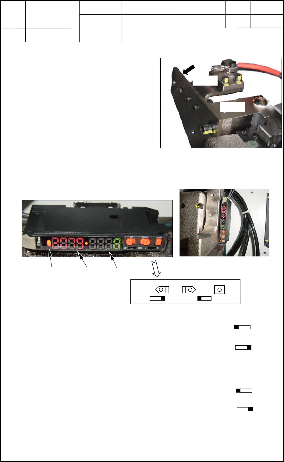
5. Setting of Lifted Feeder Detection Sensor
5.1 Attachment of Lifted Feeder Detection Sensor
(1) Attach the lifted feeder detection sensor
so that Plane A can be aligned with
Plane B. See Fig. H21.
(2) Plane A should be attached parallel to
Plane C. See Fig. H21.
At this time, the brackets should be
centered (up, down, right, and left) at
the idle hole. (Visual Check)
5.2 Adjustment of Lifted Feeder Detection Sensor Amplifier
(1) Set the mode switch to "L-ON".
(2) Adjust the emitting strength (power) of the light to emit the optimum amount of light.
(2.1) Set the [SET/RUN] switch to "RUN".
(2.2) Hold down the [MODE] button for 3 seconds.
(A numerical value appears in the sub display.)
(2.3) Confirm that the main display indicates a point close to "2000".
(3) Adjust the sensitivity on the light receiving side for the maximum one.
(3.1) Set the [SET/RUN] switch to "SET".
(3.2) Hold down the [UP] or the [DOWN] button for 3 seconds.
(A numerical value appears in the sub display.)
(3.3) Set the [SET/RUN] switch to "RUN".
(4) Check the performance of the lifted feeder detection sensor.
Use an auxiliary jig (or a block gauge) for adjustment of the lifted feeder detection
sensor and confirm at both ends of the feeder base that the emitted light can be received
at 107 mm and cannot be received at 108. 5mm.
0406-001
8-9
Plane A
Fig. H21 Attachment Position of Lifted Feeder
Detection Sensor
Plane
Plane B
Mode Display Main Display Sub Display
Fig. H23 Attachment Position
UP
DOWN
MODE
SET
RUN L D
Fig. H22 Lifted Feeder Detection
Sensor Amplifier
Fig. H26 Details of Lifted Feeder Detection
Sensor Amplifier Switch
SET
RUN
L D
SET RUN
SET RUN

Device
Name
Chip Mounter
Block Name
Page No.
Unit Name
Revision
Model ItemGXH-1
Chapter 8 Component Supply
0406-001
8-10

Chapter 9
Cutter Section
This chapter describes how to replace and adjust the cutter
section.
• Replacement of Cutter Blades
• Replacement of Cutter Axis Motor
• Replacement of Cutter Axis Servomotor Amplifiers
• Location of Limit Sensors
• Belt Tension
0406-001 9-A