SM-131-006.pdf - 第124页
Device Name Chip Mounter Block Name Page No. Unit Name Revision Model Item GXH -1 Chapter 5 Head Section 7. MSB W hole Cleaning and Lubricat ion Procedures 7.3 Operation Procedures (1) First, attach 12 nozzles in the sam…
Device
Name
Chip Mounter
Block Name
Page No.
Unit Name
Revision
Model Item GXH-1
Chapter 5 Head Section
7. MSB Whole Cleaning and Lubrication Procedures
Others (including consumption articles)
• Grease (DAPHNE EPONEX GREASE No.1)
• Screw Lock (Three Bond 1401B) <Slightly use it on the top block section and fixing
bolts.>
• New Bolts (M1.6×L3) for replacement in attaching the top block section
(Preparation: Up to the number of cleaning.)
• New Bolts (M1.6×L4) for replacement in attaching the diffusion plates (large ,small),
linear measure sensor section and the lower rotor section.
• P19 size (12P×2) for use O-ring nozzle holder section…Whole replacement: once 2 years
• P21 size (12P) for use O-ring MSB outer cover parts… Whole replacement: once 2 years
• V-packing MSB outer cover and nozzle shaft holder section (12P for each place)
… Whole replacement: once 2 years
• Rags for cleaning operation and covering the floor of the working place.
• Kerosene for cleaning of nozzle shaft
0605-001
5-22
Fig. E46
Device
Name
Chip Mounter
Block Name
Page No.
Unit Name
Revision
Model Item GXH-1
Chapter 5 Head Section
7. MSB Whole Cleaning and Lubrication Procedures
7.3 Operation Procedures
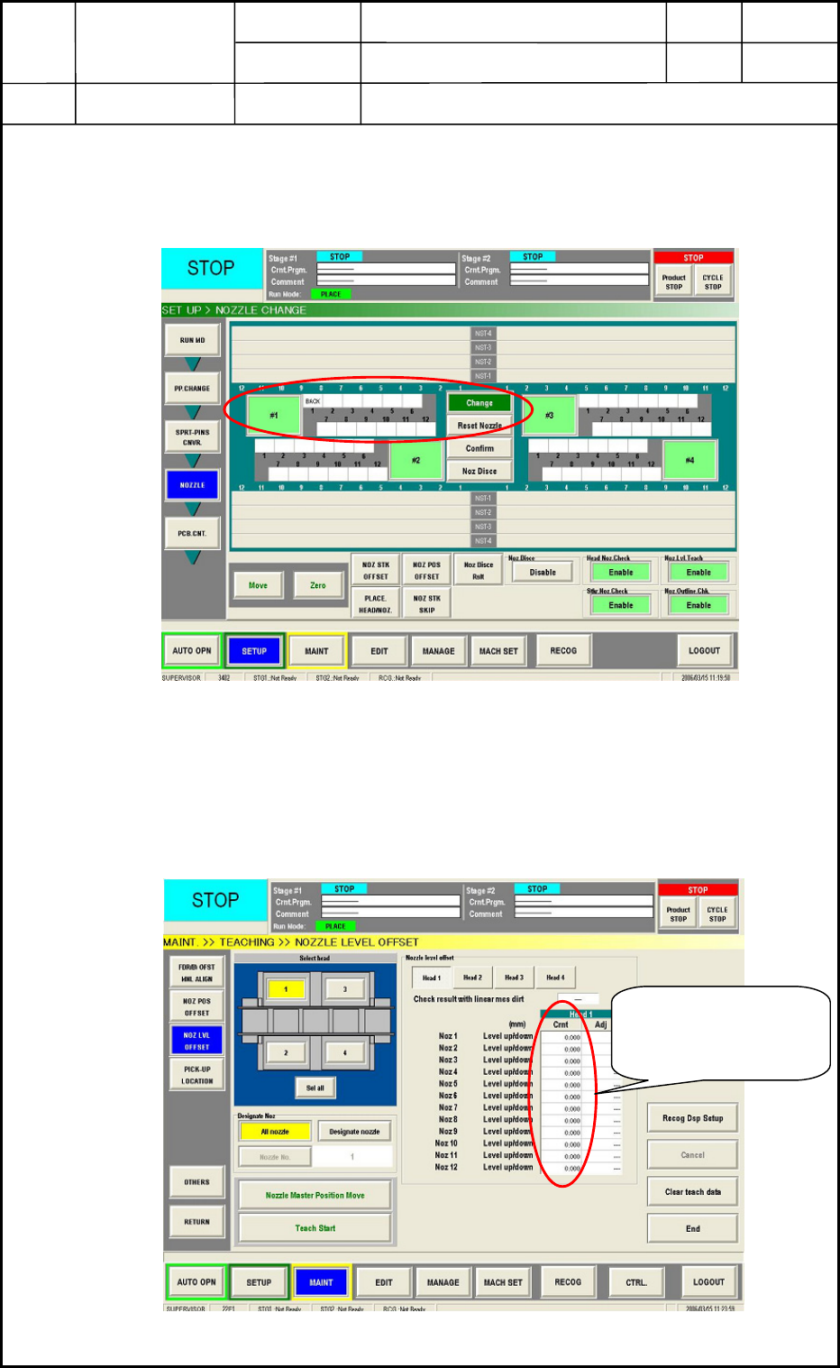
(1) First, attach 12 nozzles in the same type to the head to perform cleaning and lubrication
at the [SETUP] => [NOZZLE] tab sheet below. (No matter the nozzle types, perform the
nozzle level teaching operation.)
Fig. E47
(2) Open the [MAINT] => [TEACHING] => “Nozzle Level Offset” tab sheet below
(Fig.E48) and select the head No. and all nozzles to perform cleaning and lubrication.
Perform the teaching operation of the nozzle level offset, after that save the data.
*This data saved is used for a confirmation of the difference between “Before
lubrication” data and “After lubrication” data after cleaning and lubrication operations.
Fig. E48
Save this data of
“Before lubrication”
after teaching
0605-001
5-23
Device
Name
Chip Mounter
Block Name
Page No.
Unit Name
Revision
Model Item GXH-1
Chapter 5 Head Section
7. MSB Whole Cleaning and Lubrication Procedures
(3) Return all nozzles used for the nozzle level teaching to the stocker by the [Reset Nozzle]
button in the [SETUP] => [NOZZLE] tab sheet. Then, remove the feeder carts around
the cleaning sections to work smoothly.
(4) Turn off the machine and break the air.
(5) Detach the machine safety guard cover located to the cart upper section.
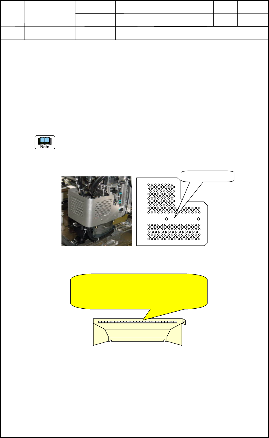
(6) Detach the head cover (See Fig. E49 below). This section has been fixed with SUS 4-
M3×L6 truss screws. (Applied 1401B screw lock)
Common use of Head covers: Head No.1 and 4, Head No.2 and 3
The head cover is set so that the cutting section turns up. Therefore, please pay attention
to the up/down directions when attaching this part (in reverse operation).
Fig. E49
Fig. E50
0605-001
5-24
Head Cover
Do not allow to hit this safety guard cover to
the linear scale located to the machine Y-axis
both sides in detaching operation. See
Volume 4 Trouble Shooting (3.3: Fig. 4A28).