SM-131-006.pdf - 第130页
Device Name Chip Mounter Block Name Page No. Unit Name Revision Model Item GXH -1 Chapter 5 Head Section 7. MSB W hole Cleaning and Lubricat ion Procedures (11) Remove 3- M1.6×L4 mounting bolts for attaching the bottom r…
Device
Name
Chip Mounter
Block Name
Page No.
Unit Name
Revision
Model Item GXH-1
Chapter 5 Head Section
7. MSB Whole Cleaning and Lubrication Procedures
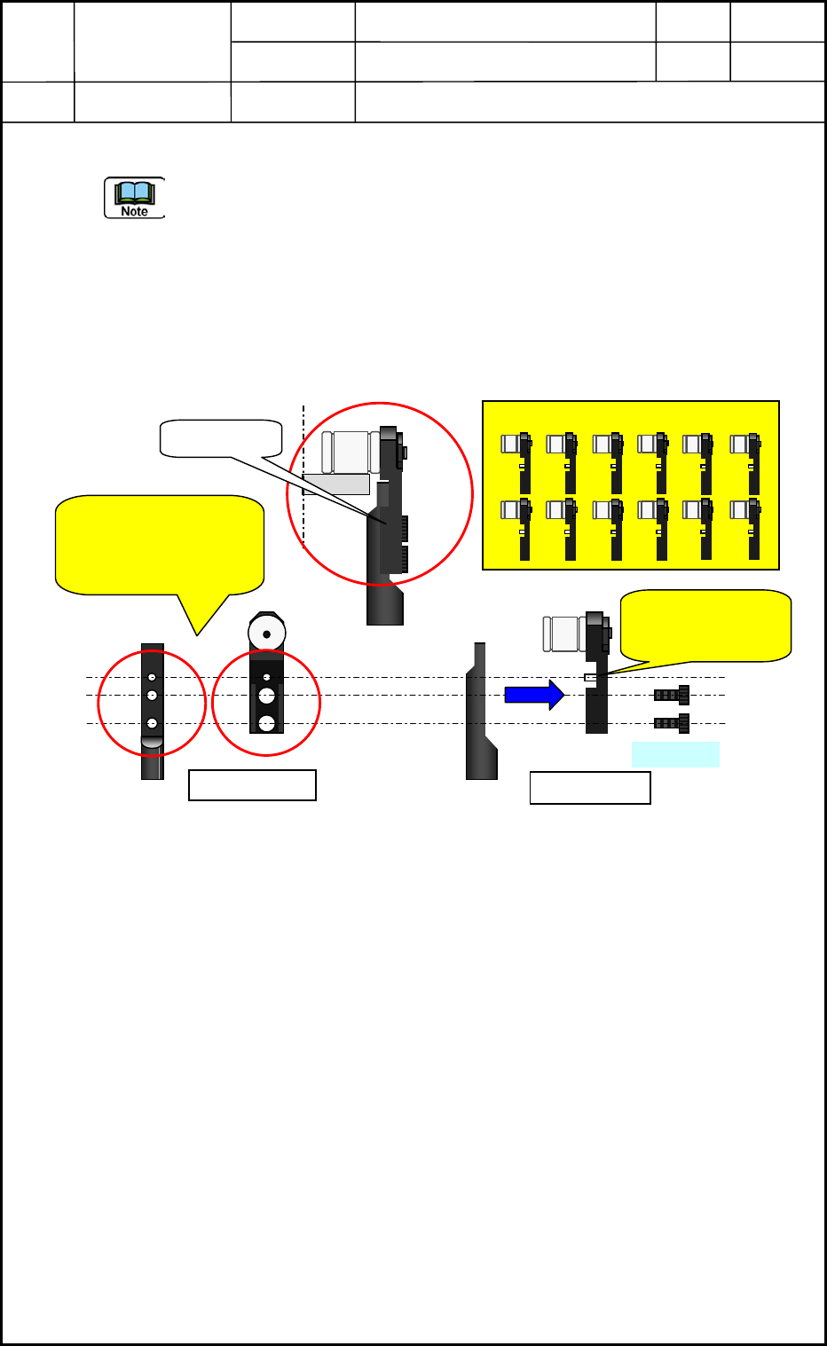
(10) Detach 12 top blocks. (See Fig. E56 below)
- Manage to distinguish the shaft setting position of the top blocks detached.
- Do not drop M1.6×L3 bolts into the head inside when removing the top blocks and, in
just case, cover the floor with the rag prepared. (Pull it out in a straight line)
- Clean up the top block detached with a rag or etc.. Check the both surfaces to attach the
shaft and the top block if the screw lock adheres and when you found the screw lock
remained, surely remove it, otherwise it may bring about some troubles.
Fig. E56
Front View
Side View
Top Block
When you found the
screw lock remained
around here, please
remove it cleanly.
M1.6×L3
1 2
3
4 5 6
7
8 9 10 11 12
Line up these top blocks in order.
Pull out it in a
straight line and
detach it.
0605-001
5-28
Device
Name
Chip Mounter
Block Name
Page No.
Unit Name
Revision
Model Item GXH-1
Chapter 5 Head Section
7. MSB Whole Cleaning and Lubrication Procedures
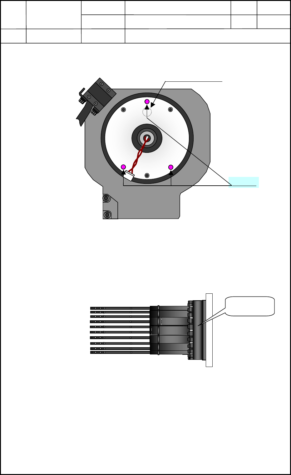
(11) Remove 3-M1.6×L4 mounting bolts for attaching the bottom rotor as shown in
Fig. E57 and detach the nozzle shaft assy (bottom rotor) from the DD motor.
Fig. E57
The following Fig. E58 is showing the condition that the nozzle shaft assy (bottom rotor)
has already been removed from the DD motor.
Fig. E58
No.1 Nozzle Position
View of head Bottom Surface
No.1 ノズル
M1.6×L4
Nozzle Shaft
Assy
0605-001
5-29
Device
Name
Chip Mounter
Block Name
Page No.
Unit Name
Revision
Model Item GXH-1
Chapter 5 Head Section
7. MSB Whole Cleaning and Lubrication Procedures
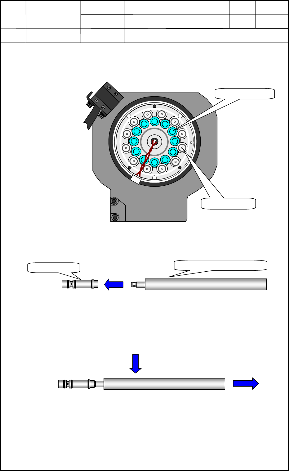
(12) Remove 12 nozzle holders from the DD motor (upper rotor) with a nozzle holder
inserting Jig.
* This nozzle holder inserting jig has become a screw type so, tuck the nozzle holder
inserting jigs in the nozzle holders for each 10-sections and pull out the nozzle
holders together with the jigs.
Fig. E59
Nozzle Holder
Vacuum Valve
View of Head Bottom Surface
Nozzle Holder Inserting Jig
Nozzle Holder
0605-001
5-30