SM-131-006.pdf - 第103页
Device Name Chip Mounter Block Name Page No. Unit Name Revision Model Item GXH-1 Chapter 5 Head Section 1. Replacement of Head Unit 1.1.2 Detachment of Head Unit (1) When the four bolts (M5L16) are remove d, it becomes p…
Device
Name
Chip Mounter
Block Name
Page No.
Unit Name
Revision
Model ItemGXH-1
Chapter 5 Head Section
1. Replacement of Head Unit
1.1 Detachment of Head Unit
If the head unit can be zeroed, the power supply should be shut down at the origin
position.
(Especially the HL axis)
.
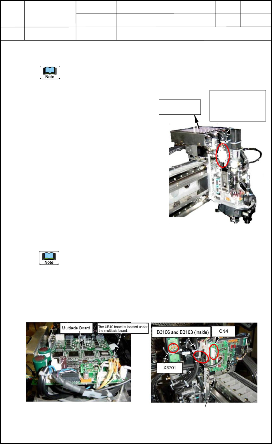
1.1.1 Disconnection of Head Cover Wires
(1) Detach the head cover.
(Upper Area on Front Side)
(2) Detach the cover for the linear measure
sensor board (amplifier). (Fig. E1)
CN4 (white 8 pins) on the board must
also be disconnected.
(3) Cut the tie wraps of the camera cable and
the wires for the lighting. (Several Places)
(4) Disconnect the camera cable from the
camera.
(5) Disconnect the nylon connectors (6 pins)
for the lighting wires.
(One of the connectors is covered with
tube (E61).)
(6) Disconnect two nylon connectors B3106
and B3103 (4 pins).
It is required to detach the multiaxis board because the connectors are located under
the board. (Fig. E2)
When the connectors are not visible, yet after the multiaxis board is etached, it is
also required to detach the UB19 board located under the multiaxis board.
(7) Disconnect the four nylon connectors B3101, B3102, B3104, and B3105. (located
beside the NL Axis)
(8) Disconnect J1 Connector X3701 (6 pins) from the slip ring section.
(9) Detach the two pneumatic pipes.
0406-001
5-1
Head Cover
Connector No.
B3101, B3102,
B3104, B3105
Fig. E1 Head Unit Section
Fig. E2 Head Control Board
Fig. E3 Linear Measure Sensor
Amplifier Board
Device
Name
Chip Mounter
Block Name
Page No.
Unit Name
Revision
Model ItemGXH-1
Chapter 5 Head Section
1. Replacement of Head Unit
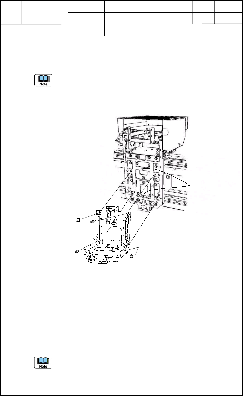
1.1.2 Detachment of Head Unit
(1) When the four bolts (M5L16) are removed, it becomes possible to detach the head
unit from the head mounting section of the beam.
(a) The positioning pins may interrupt the detachment slightly.
(b) Two people are required for this work.
One person should hold the head unit securely.
(c) When the head unit is attached, be sure not to touch the HL/NL origin and limit
photosensors. Otherwise, the photosensors may be damaged.
1.2 Attachment of Head Unit
1.2.1 Attachment of Head Unit
Attach the head unit to the head mounting section with four bolts (M5L16) as shown in Fig.
E4.
1.2.2 Connection of Head Cover Wires
(1) Follow the reverse order of the steps described in "1.1.1 Disconnection of Head
Cover Wires" for the wiring and piping.
The wires must be bundled together.
(2) Attach the head cover.
(a) Be sure to bundle the excessive wires together on the head multiaxis board, so
that the wires cannot be moved.
(b) When the head unit is attached, be sure not to touch the HL/NL origin and limit
photosensors. Otherwise, the photosensors may be damaged.
Fig. E4 Head Unit Section
M5L16 (4 pcs.)
Positioning Pins
0406-001
5-2

Device
Name
Chip Mounter
Block Name
Page No.
Unit Name
Revision
Model ItemGXH-1
Chapter 5 Head Section
1. Replacement of Head Unit
1.3 Operation Check
Check if the power can be supplied normally and the zeroing and manual axis operations
can be performed normally.
Check the connection of the pneumatic and vacuum pipes.
1.4 Adjustment of Offsets
Adjust the following offset items.
1.4.1 Manual Offsets
(1) Head Up/Down Offset
(2) Feeder (A) Offset (L U/D)
1.4.2 Automatic Offsets
(1) Master Nozzle Level Offset
(2) PEC Recognition Camera & Beam Offset
(3) Component Recognition Camera Offset (Offset Teaching)
(4) Head Rotational Angle Axis Offset
(5) Head Rotational Center Offset/Reference Mark Position Offset
(6) Fly Recognition Camera Offset
(7) Nozzle Position Offset
(8) Nozzle Level Offset
(9) NL-Axis Origin Offset
0406-001
5-3