SIPLACE Station Software 7xx to 714 介绍.pdf - 第112页
Station Software 7xx to 714.0 (R20-2) / Feature Description 11/2020 Edition 112 7.38.8 Gra ph ical Display of the Feeder Pick-up Position Compatible mode: Complete In the Details view of a feeder, a dialo g can be opened…
Station Software 7xx to 714.0 (R20-2) / Feature Description 11/2020 Edition
111
If the pick-up angle has been changed and the pick-up point is non-central, the pick-up location
possibly will be changed, too. Thus, the pick-up location might be located outside of the allowed
area. After the pick-up angle has been changed, the values cannot be saved until the XY position
has been adjusted so that the pick-up location is located within the allowed area again.
The limitation of the setting area refers to the nominal position. If the pick-up position has been
taught to a point outside of the allowed area on the Machine service activity level, an operator on
a lower activity level may also teach outside the allowed area. However, only changes in the
direction of the nominal position are allowed. For this operator, it is not allowed to move farther
away from the nominal position.
NOTICE
After the pick-up position has been changed in Y direction, it will not be checked if all
head segments can pick up from there, because at the teaching time, the segments
which will pick up from there during placement later might not be known. The possibility
to go there with the z-axis depends on the used segment.
7.38.7 Saving the XY Pick-up Position
Compatible mode: Not supported
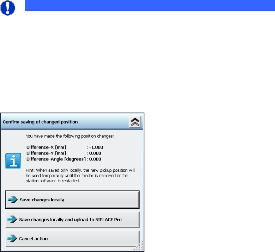
After the XY pick-up position or the pick-up angle have been changed and the Save button has
been clicked in the correction dialog of the pick-up position, the taught offsets will be displayed as
follows:
Figure 7-44: Confirmation dialog for changed XY pick-up position / pick-up angle
If uploading is allowed under the current handling option, you can select if the changed position
parameters shall be saved locally at the station only (Save changes locally button) or additionally
uploaded to SIPLACE Pro into the local setup data (Save changes locally and upload to
SIPLACE Pro button).
If uploading is not allowed under the current activity level, the Save changes locally button is
displayed only.
Station Software 7xx to 714.0 (R20-2) / Feature Description 11/2020 Edition
112
7.38.8 Graphical Display of the Feeder Pick-up Position
Compatible mode: Complete
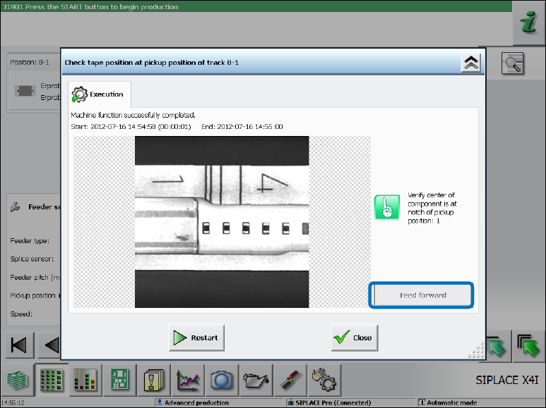
In the Details view of a feeder, a dialog can be opened via the Check tape position at pickup
position … button in which the camera image of the pick-up position with all pick-up position
markings (notches) on the feeder is displayed.
Figure 7-45: Details view of a feeder
Fine Adjustment of the Pitch at the Feeder
With the Feed forward button, the smallest possible pitch can be set at the feeder. This concerns
the control of the feeder hardware only and has no other effect.
The purpose of this function is to position the feeder so that the tape pocket is possibly centered to
the recommended pick-up position / visible feeder notch.
The pick-up position can be set on the GUI for the following (tape) feeders:
– 4 mm – 104 mm X-feeders
For feeder types < 12 mm, the current pitch in the feeder must be set to > 4 mm to achieve the
same functionality as on the operator panel of the feeder and to avoid incorrect settings for
smaller pitches.
– 12/16 mm X Smart Feeder
Dependent of the current activity level, the feeder parameter can be changed in the lower area in
the Details view of a feeder.
Station Software 7xx to 714.0 (R20-2) / Feature Description 11/2020 Edition
113
Changing the pick-up position will have the following consequences:
– The changed setting is transmitted to the feeder that then presents the component at the new
defined position. To see the changed position, the operator must restart the Check tape
position at pickup position dialog.
– If uploading is allowed, the changed pick-up position settings are immediately uploaded to
SIPLACE Pro into the local setup data.
After the feeder has been stepped with the Feed forward button, a new camera image of the pick-
up position will be automatically displayed. If necessary, the pick-up position must be re-taught in
the Position correction dialog.
7.38.9 Tape Pocket Detection of Component Shape 0603
Compatible mode: Complete
The tape pockets of component shape 0603 have been integrated in the default workflow of the
tape pocket detection. In connection with this change, the behavior in error cases has been
modified, too. After a pocket detection error has occurred, the software still tries to pick up the
component. If the component cannot be picked up, the machine stops with a vacuum error.
Additionally, the Check and teach feeder pocket shapes button is highlighted in red. If this button
is selected, a dialog is opened in which the tape pocket detection can be performed manually or be
skipped.