SIPLACE Station Software 7xx to 714 介绍.pdf - 第156页
Station Software 7xx to 714.0 (R20-2) / Feature Description 11/2020 Edition 156 NOTICE When upgrading from a previous station software version to the 70 8.0 version, segments with the Disabled or Not used state s will be…
Station Software 7xx to 714.0 (R20-2) / Feature Description 11/2020 Edition
155
9.7.2 Statistics Data
The statistics data for the dp-axes of the C&P20A placement heads is read from the subsystem
and stored in the CP20DPDump.xml file. As of this station software version, the statistics data is
additionally recorded for the following subsystems in the same way:
● C&P20 P pressure control valve
● CPP star axis
● CPP z-axis
In contrast to the statistics data for the dp-axes of the C&P20A placement heads that is only
updated during the machine start, the additional statistics data is cyclically loaded from the
subsystems every 24 hours. The data is stored in the C:\Sirio\Work\eSW folder. A separate file is
created for each subsystem.
9.8 New State for Segments of C&P Placement Heads
Compatible mode: Complete
If placement quality and pickup problems occur, the operator frequently disables segments of C&P
placement heads what often results in exchanging the module. However, in many cases the
module is not defective, but the problem was caused by a worn nozzle or filter disk.
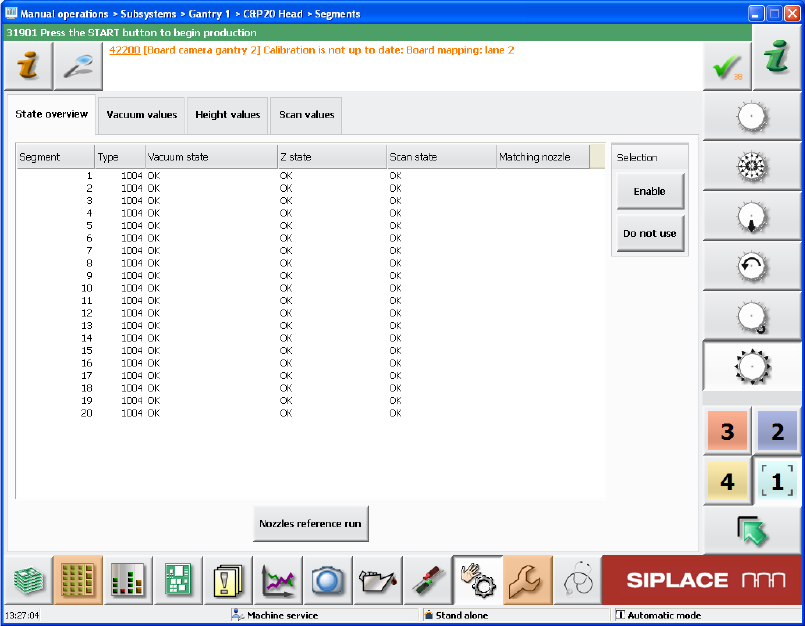
In such cases, the new Do not use state can be set for the head segments in the Manual
operations in the State overview view. The Not used state is assigned to the respective
segment. Defective segments first must be set to Do not use and additionally disabled via the
Disable button. Via the Enable button, the segment can be put into operation again.
Figure 9-4: Setting the state for segments
Station Software 7xx to 714.0 (R20-2) / Feature Description 11/2020 Edition
156
NOTICE
When upgrading from a previous station software version to the 708.0 version, segments
with the Disabled or Not used states will be automatically reset to the Enabled status! If
required, the state has to be changed manually again for such segments.
9.9 Endurance Run with Components
Compatible mode: Complete
To test parts and modules adequately on early failures before a machine is delivered, an
endurance run has been developed for a possibly real placement mode.
In the endurance run, components are picked up and placed on a board as specified in SIPLACE
Pro. Thereafter, the components are removed from the board in the same sequence they were
placed and recycled before the cycle restarts. Special components, waffle pack trays and boards
are used for this. The waffle pack tray is fed via the conveyor. For higher robustness, fiducials can
be defined on the waffle pack tray.
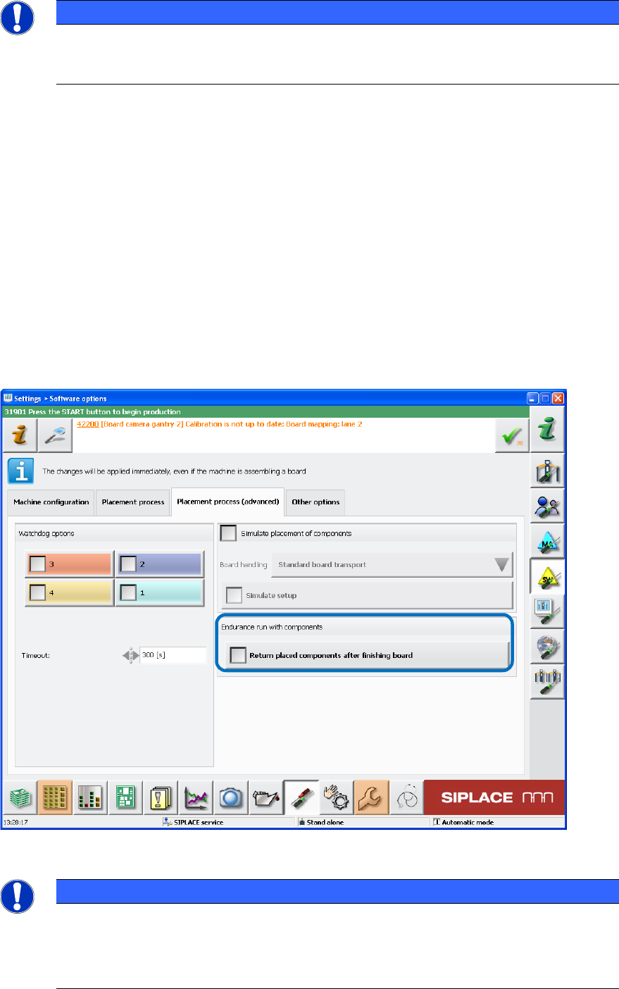
The endurance run will run automatically and can be enabled under Settings – Software options
– Placement process (advanced) – Endurance run with components as of the Machine
service activity level.
Figure 9-5: Endurance run with components
NOTICE
For operators of previous station software versions:
The already available settings for endurance run without components (Simulate
placement of components) have been moved from the Placement process tab to the
new Placement process (advanced) tab.
Station Software 7xx to 714.0 (R20-2) / Feature Description 11/2020 Edition
157
9.10 Triggering Automatic Error Reports
Compatible mode: Complete
Automatic error reports can be triggered for unplanned machine stops during reference runs and
dry-runs in this station software version. For this, the monitoring of the head axes must be set
manually. With the recorded data it is possible to detect and analyze the causes of malfunction and
fix the faults faster. The monitoring function is available for the SIPLACE Service activity level.
At first, the desired endurance run must be started under Settings – Software options –
Placement process (advanced). When all head axes are running, the monitoring must be
configured.
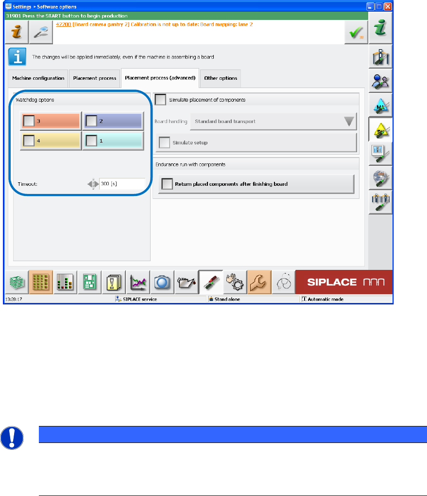
The head axes to be monitored must be selected manually and if required, the monitoring time can
be changed for the current endurance run. Then the monitoring must be enabled via the Watchdog
options check boxes. The set head axes also remain stored after a machine restart.
Figure 9-6: Enabling monitoring
The selected head axes will be monitored after the monitoring has been enabled. If one of these
head axes should not start after the set time, a respective automatic error report will be triggered.
If new / other endurance runs are started or an automatic error report has already been triggered,
the monitoring must be enabled again.
The monitoring must be disabled either via the Watchdog options check boxes or the Stop
button.
NOTICE
If a program is used in dry-run, it must be considered that the placement program
specified in SIPLACE Pro does not contain longer pause times for a head axis as the set
time in the monitoring function. Otherwise, the monitoring function would trigger the error
report.