SIPLACE Station Software 7xx to 714 介绍.pdf - 第64页
Station Software 7xx to 714.0 (R20-2) / Feature Description 11/2020 Edition 64 The XML file is available under t he C: \Sirio\Types direc tory on the service desktop and may b e edited by an XML editor, if necessary. The…
Station Software 7xx to 714.0 (R20-2) / Feature Description 11/2020 Edition
63
7.4 Automatic Pin Positioning with Smart Pin Support
For many products it is necessary to support the board with so-called Support Pins in the
processing area. The support pins are placed on the lifting table and are kept at the defined
position by a magnet.
Manual override in the clamping area is very non-ergonomic and thus it is difficult to position the
support pins accurately by hand. Therefore an automatic pin positioning has been realized for the
SX1/SX2 V2 placement machine that is supported by this station software version. The support pin
positioning is performed by a pin picker that may position a definable number of support pins on the
lifting table. The support pin positions are defined for the recipe in SIPLACE Pro.
When the recipe is produced on the line, the support pins are automatically positioned before
production begins. Already available support pins on the lifting table may then be brought to new
positions. Missing support pins are taken from a pin magazine. If too many support pins are
available on the lifting table, they will be put back into the pin magazine. In the Setup view it is
possible to check the current support pin positions and to place or remove support pins.
Detailed information on Smart Pin Support can be found in the corresponding user manual,
item no. [00197001-01], and in the online help files to SIPLACE Pro and the station software.
Restrictions
– No collision checks in case of manual configurations on the Machine service and SIPLACE
service activity levels.
– Support pins cannot be placed before all boards in the processing area have been produced
and unloaded from the machine. Loaded boards are blocked in the input section.
– In case of barcode mode together with support pin positioning, a barcode change results in a
long changeover time, as the support pin positioning does not start until all boards have been
unloaded (except for the boards in the input section).
7.5 Revision of SSI Interface for OIS Events
The SSI interface has been revised in order to improve the support of I-Placement mode by the
OIS events. Especially, the support has been improved for the monitoring data in connection with
the "Continue production when track is empty" feature.
7.6 New SIPLACE Glue Feeder Feeder Type
The station software supports the new SIPLACE Glue Feeder feeder type. SIPLACE Glue Feeder
is an X-feeder with which glue dots can be applied onto the rear side of the component just before
the component gets placed.
The glue dots are modeled in SIPLACE Pro by defining the X-position, Y-position and the diameter
of each glue dot on the component. Multiple different glue dots can be defined for a single
component.
The process parameters of a glue dot are stored in a characteristic line at the station. The
corresponding XML file contains the glue name, the glue dot diameter, the number of shots per
glue dot, the Z-height of the jet and the fixed defined frequency of the shots.
The process parameters per glue dot are assigned at the station as follows:
Via the definition for the glue dot diameter in SIPLACE Pro the closest glue dot diameter in the
characteristic line is defined (always rounded down). The defined number of shots, the Z-height
and the frequency of the glue type are the process parameters that are passed on to the pickup
process and the SIPLACE Glue Feeder.
Station Software 7xx to 714.0 (R20-2) / Feature Description 11/2020 Edition
64
The XML file is available under the C:\Sirio\Types directory on the service desktop and may be
edited by an XML editor, if necessary. The process parameters can only be modified, copied or
distributed at the station by a SIPLACE service engineer. For this the Service (SIPLACE) activity
level is required. After the XML file has been changed, the station has to be warm-started or the
placement machine rebooted.
After the job has been downloaded to the station, the operator can measure the X-, Y- and Z-
positions of the jet and check if the jet is soiled via SIPLACE Vision (manually in the Manual
Operations for the feeder) The X- and Y-positions are measured with the PCB camera and the Z-
position with a nozzle and a reference plate.
The station software generates a glue job for each glue dot during which the following steps are
performed:
– The component is moved to the X-/Y-positions to apply the glue dots (considering the
measured X-/Y-offsets of the jet).
– The component is moved to the configured Z-position (XML file) to apply the glue dots
(considering the measured Z-height of the jet).
– The component presence is checked by SIPLACE Vision to ensure that the glue dots are not
applied onto an empty nozzle.
– The glue dots are applied onto the component using the process parameters that are stored in
the characteristic line at the station.
– The component presence is checked again by SIPLACE Vision to ensure that the component
did not get out of place during the glue process. If a measuring error occurs during the
component check by SIPLACE Vision, the component is rejected, i.e. components from a tray
are not returned into the tray.
– The Z-axis is moved to the initial position.
A collision check of the process height is performed before the glue process starts. At risk of
collision the glue process is rejected or the component is not picked-up.
Glue dot inspection and teaching by SIPLACE Vision
In order for SIPLACE Vision to detect and evaluate a glue dot, a reference image of a component
will be acquired right before the glue is applied onto the component.
During a measuring job with glue dot inspection, there will be a check for each glue dot, if:
– The glue dot exists.
– The size is within the defined tolerance, i.e. if the measured surface of the glue dot lies
between the minimal and maximal circular area in the model.
– The glue dot lies within the defined "target area": a rectangular target area can be defined in
the model. The inspection checks if the glue dot is completely positioned within this target area.
An error message is displayed if the glue dot touches the border of the target area.
Optionally, a separate lighting can be set for the glue dot inspection.
The following glue dot parameters may be modified in the GF Editor at the station:
– Inspection
– Tolerance
– Target area (X/Y/size)
Station Software 7xx to 714.0 (R20-2) / Feature Description 11/2020 Edition
65
The component onto which the glue dots will be applied can be manually taught. For this, the
operator selects the component (that is marked accordingly) from the component list. A dialog box
is opened in which the operator can decide, whether the glue dots shall be applied onto the
component before teaching or not.
SIPLACE Vision creates automatic output files for the components with glue dots. With these files
the operator can perform the inspection offline.
The glue dot inspection is optional and can be activated / deactivated in SIPLACE Pro.
NOTICE
Calibration of the Glue Feeder
The Glue Feeder has to be calibrated each time the machine is booted or the Glue
Feeder is inserted or removed.
Detailed information on SIPLACE Glue Feeder can be found in the correspondent user manual,
item number 00197219-01 and in the online help files to SIPLACE Vision and station software.
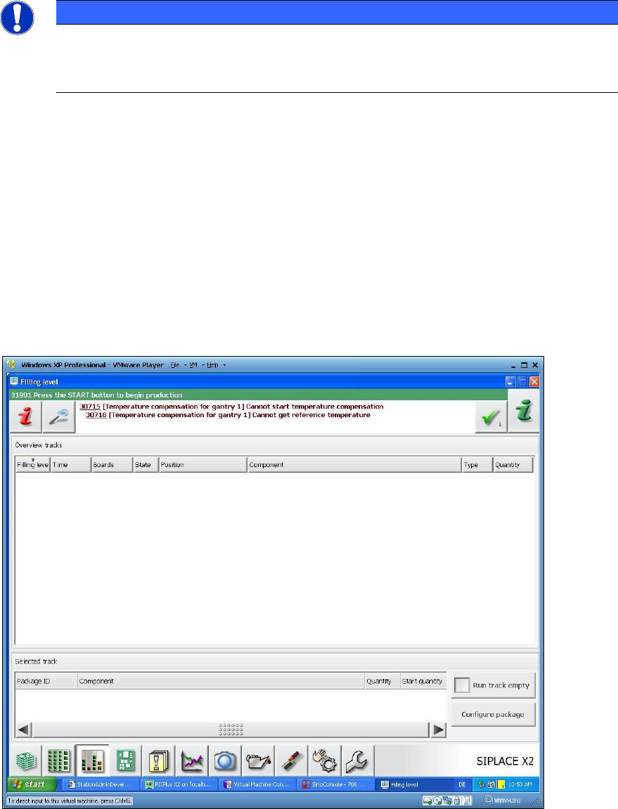
7.7 Display of Remaining Time in the Filling Level View
With this feature the remaining time is calculated as for the components required to produce the
boards completely. The remaining time until a feeder gets empty is calculated by means of the
component levels from Setup Center, the job data from SIPLACE Pro and / or the panel at the
station.
The remaining Time in [hh:mm] and the number of boards to be produced are displayed in the
Filling level view on the GUI of the station software. After this time is elapsed, the boards cannot
be completely produced.
Figure 7-1: Filling level view