SIPLACE Station Software 7xx to 714 介绍.pdf - 第162页
Station Software 7xx to 714.0 (R20-2) / Feature Description 11/2020 Edition 162 9.18 Power Supply (SMPS) – Status Display on the GUI Compatible mode: Complete The SMPS ( S witched M ode P ower S upply) offers advanced di…

Station Software 7xx to 714.0 (R20-2) / Feature Description 11/2020 Edition
161
Features (V708.1: Compatible Mode V707.3)
9.16 Reading Individual Barcode Fiducials with Board Camera
Compatible mode: Not supported
For traceability purposes, many components have a 2D-barcode on top of itself or next to the
component pocket at the tape.
As of this station software version, such individual barcode fiducials can be read by the board
camera during pickup and then assigned to the placement position (Reference Designator) in the
provided traceability data.
The option must be defined and enabled in SIPLACE Pro.
Prerequisites
– The "Reading Barcode recognition with PCB Camera" license is available and enabled.
– Traceability is enabled.
If the option is enabled but reading the barcode fiducial fails, the component will be picked up and
rejected in the respective reject bin. As soon as the set number of repicks is achieved, the feeder
gets disabled and a detailed error message is displayed on the GUI. The operator is prompted to
perform an additional teaching. However, the operator is free to ignore this prompt and may
continue placing the components anyway.
9.17 C&P20 P Placement Head on SIPLACE SX1/SX2 (V2)
Compatible mode: Not supported
This station software version supports the C&P20 P placement head on the SIPLACE SX1/SX2
(V2) placement machine.
The functionality and configurations that are valid for the C&P20 placement head are supported for
the C&P20 P placement head, as well.
NOTICE
The C&P20 P and C&P20 placement heads should not be combined at one station!
Station Software 7xx to 714.0 (R20-2) / Feature Description 11/2020 Edition
162
9.18 Power Supply (SMPS) – Status Display on the GUI
Compatible mode: Complete
The SMPS (Switched Mode Power Supply) offers advanced diagnostic checks. As of this station
software version, the SMPS states are additionally displayed on the GUI.
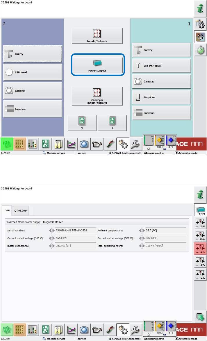
As of the Machine Service activity level, the new Power supplies button is available under
Manual operations – Subsystems.
Figure 9-7: Subsystems dialog – Power supplies
If this button is selected, a new dialog opens in which the states of the power supplies and fuses
are displayed.
Figure 9-8: Diagnosis Master dialog – CAP tab
Station Software 7xx to 714.0 (R20-2) / Feature Description 11/2020 Edition
163
In the CAP tab, data related to the Diagnosis Master is displayed.
The power supplies (SMPS) and fuses (24V, 27V etc.) can be selected to the right. The fuses are
grouped by their respective voltage.
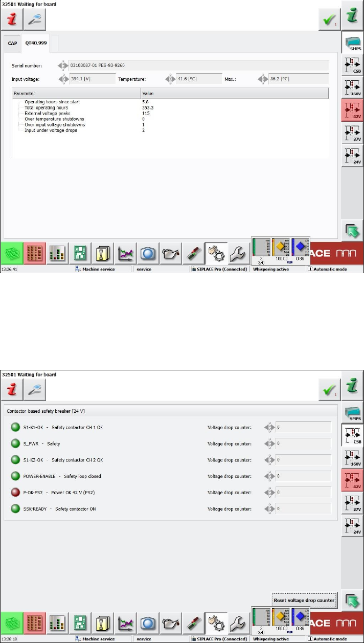
Figure 9-9: Diagnosis Master dialog – SMPS tab
In the SMPS tab (here: QT40.999), data related to the respective power supply is displayed. There
may be two tabs, one for each possibly existing power supply. If only one power supply exists, the
second tab is disabled.
Sensors related to the safety circuit of the machine are grouped in the CSS view (Contactor-based
Safety Switch-off) to the right.
Figure 9-10: CSS view