SIPLACE Station Software 7xx to 714 介绍.pdf - 第241页
Station Software 7xx to 714.0 (R20-2) / Feature Description 11/2020 Edition 241 – New I/O ports dialog The dialog displays the inp ut and output states of the sensors. This dialog is only visible as of activity level Mac…
Station Software 7xx to 714.0 (R20-2) / Feature Description 11/2020 Edition
240
The leveling assistant helps the user to adjust the z-height of the vacuum tooling. Additionally,
this tool is used to set up the planarity of the vacuum tooling surface and adjust it vertical to the
z-axes of the placement heads.
To the left, all available surfaces are displayed in a tree view. Currently, it contains entries for
adjusting the z-height of the vacuum tooling and measuring the height of the conveyor rail.
By selecting one of the available surfaces, a short description of the surface and a list of the
positions where the z-height will be measured are displayed to the right. The positions have the
same names as those that are used when the machine positions are taught. This makes it
easier for the user to identify the position in case it must be taught or if the user e.g. wants to
check that the position is on the surface and not directly above a hole.
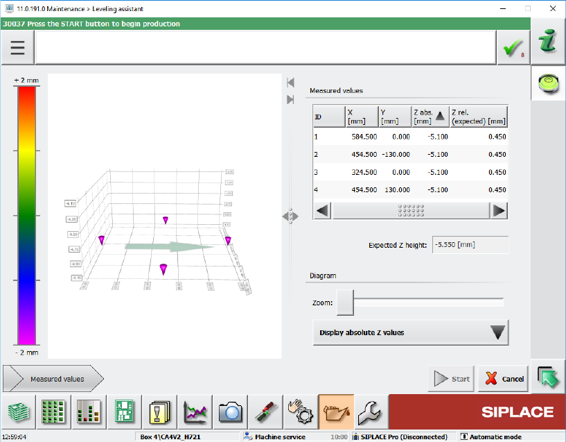
The measurement is started by pressing the Start button. If the measurement is successful, the
Measured values are displayed automatically. Otherwise an error message is displayed.
Figure 12-6: Measured values
In this view the measurement can be repeated at any time by pressing the Start button again.
An image displays the surface at the mean z-value, allowing the user to see which positions
are below or above the mean value. The user can select if the chart shall display absolute or
relative values. The relative values are always relative to the mean z-value.
12.17 SIPLACE JTF-ML2 – Enhanced Functionality
The functionality has been enhanced for the SIPLACE JTF-ML2 tray feeder. The Manual
operations dialog for the feeder has been changed as follows:
– Functions dialog
Reset buttons have been added to the existing Transfer position – Teach position and Refill
position – Teach position functions for the lifting axes to reset the respective position to the
factory settings.

Station Software 7xx to 714.0 (R20-2) / Feature Description 11/2020 Edition
241
– New I/O ports dialog
The dialog displays the input and output states of the sensors. This dialog is only visible as of
activity level Machine service.
Additionally, the endurance run for trays has been added to the Maintenance – Endurance run
dialog for the SIPLACE JTF-ML2 feeder.
NOTICE
Manual functions are not prevented with components in the tray feeder. There is no
check in the station software. The operator is responsible for whether the tray feeder is
empty or not.
12.18 Multiple Road Runner Feeders – Improved Handling
A new behavior has been implemented to improve the performance and minimize the waiting time
for multiple Road Runner feeders set up on one table.
An attribute has been added to this feeder type in SIPLACE Pro, containing one of the following
pickup strategies:
– Pickup as specified by the optimization, i.e. pickup from one Road Runner feeder until it has no
more prepared components.
– Preferring available feeders / levels, i.e. if one Road Runner feeder must prepare components,
pickup from the other Road Runner feeder until this has to prepare components.
The respective pickup strategy will be explicitly switched on with the download data of SIPLACE
Pro at the station. The placement order will not be affected.
12.19 "The Hermes Standard" – Board Locking Process
A board locking process has been introduced for lines using the "The Hermes Standard". This
means that a board in the previous machine may be locked after barcode reading and not moved
into the placement machine using "The Hermes Standard" until the board is unlocked, e.g. by the
BoardGateKeeper.
If "The Hermes Standard" is active and a barcode exists, the board remains in the previous
machine. If no barcode is available, the board remains either in the input section or in the
placement area depending on where the barcode is read.
The BoardGateKeeper (or any client that can lock the board) can now apply one of the following
behaviors:
– The board is moved into the machine and gets placed.
– The board remains in the previous machine and must be removed from there.
– The board is aborted and moved to the end of the line.
If the board is locked, a Detailed Error will be displayed as a warning.
The lock cause is displayed (e.g. invalid barcode, no BoardGateKeeper reaction) and the operator
can select one of the following actions:
– Release lock, move board into machine and cancel board
– Release lock and process board as usual
Station Software 7xx to 714.0 (R20-2) / Feature Description 11/2020 Edition
242
12.20 Front-Back-Offset Measurement
The station software supports the new Front-Back-Offset Measurement when placing chips with
the Fan-out Panel Level Package (FOPLP) technology. It measures the offset between the bottom
outline of a die and the electrical connection on the top. The Front-Back-Offset Measurement is
supported on the CA4 placement machine together with the C&P20 M and CPP placement heads.
The new SST40 stationary camera with glass plate has been introduced for this measurement. The
camera has to be manually mounted for each station. The die is placed on the center of the glass
plate for measurement. First the camera measures the bottom outline of the die. The result of this
measurement is used to correct the estimated position of the structure on the top side which is
measured afterwards. The difference between the expected and the measured position of the
structure is the so-called "die offset".
The dies to be measured from a wafer must be selected in SIPLACE Pro. Each die that shall be
measured by the Front-Back-Offset Measurement must be enabled. The dies which are used for
Front-Back-Offset Measurement will be picked-up at first and used to compute the offset average.
The resulting offset is used for all other dies of this wafer to place the dies correctly.
An individual wafer can be selected in the Setup view of the SIPLACE Wafer System on the station
software GUI. If Front-Back-Offset Measurement is activated for dies provided by this wafer, the
following specific data will be displayed for the wafer:
– Offset and deviation
– Number of measured dies
– Number of measured dies with a minimum percentage of measured dies with "good result". I.e.,
the measurement was successful, and the measurement result was used to compute the offset.
All component shapes must be complete before production starts. Teaching during production is
not supported.
12.21 Checking GigE Camera Connections – Enhanced Functionality
The functionality to check GigE camera connections has been enhanced in the Maintenance view
under Camera Verification – Check all camera connections. In addition to failed connections, a
possibly existing transmission error rate for working connections will be displayed.
The transmission error rate is displayed in DPM (Defects Per Million).
1 DPM = from one million transmitted data packages, one package was faulty.
A transmission error rate < 10 DPM is no problem but significantly higher values indicate a
hardware problem of the transmission link. In this case, the plug of the trailing cable should be
checked. Possibly, the VBI (Vision Base Interface) and / or VHI (Vision Head Interface) must be
exchanged.