SIPLACE Station Software 7xx to 714 介绍.pdf - 第92页
Station Software 7xx to 714.0 (R20-2) / Feature Description 11/2020 Edition 92 Features (V706.1 : Compatible Mode V705.05 ) 7.27 Compatible Mode The 706.1 station software version can be used as Ve rsion 705© in compatib…
Station Software 7xx to 714.0 (R20-2) / Feature Description 11/2020 Edition
91
The default values of the two options depend on the position of the machine within the line:
– Automatic product change is enabled by default on all machines that have a preceding
machine in the line.
– Stopping in the output section is enabled by default if automatic product change is enabled
AND the machine is the last one in the line.
NOTICE
– Changing the Product change option might affect the default of the other option!
– In dual conveyor mode, these options can only be set for both lanes.
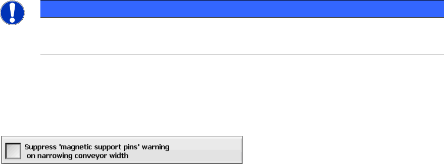
7.25.2 Suppress 'magnetic support pins' Warning on Narrowing the Conveyor
Width
Under Settings – GUI settings you can select to suppress this warning:
The default is to prompt the operator to remove the support pins. However, this option will not be
displayed on machines equipped with Smart Pin Support.
7.26 Displaying Parallel States by the Lamp Indicators
The towers of the X-, SX- and DX-series placement machines are equipped with two lamp
indicators (one on each side of the machine). These lamp indicators are either two-colored (green /
white) or three-colored (green / yellow / red). With the aid of the different states of the single lamp
indicators (including the flashing frequency) the operator can recognize the machine status (i.e.
production, waiting state, error type etc.).
Parallel states are possibly displayed at the same time by the two-colored lamp indicator system.
E.g., if a reference run, a width adjustment, a manual function or a calibration is performed during
production, the white lamp indicators flash briefly and the green one normally at the same time.
As of this station software version the two lamp indicators do not flash at the same time anymore, if
a board cannot be moved into the succeeding machine or system (oven/AOI), e.g. because of a
jam in the succeeding system.
No parallel states are displayed by the three-colored lamp indicator system.
The meaning of the lamp indicators is explained in the online help of the station software.
Station Software 7xx to 714.0 (R20-2) / Feature Description 11/2020 Edition
92
Features (V706.1: Compatible Mode V705.05)
7.27 Compatible Mode
The 706.1 station software version can be used as Version 705© in compatible mode on placement
machines that do not run with the 706.x station software only. I.e., the compatible mode may be
used on an SX1/SX2 but not on an SX1/SX2 V2 placement machine.
This means that the new functions of the current version can be used in the compatible version as
far as possible.
The visibility and functionality of the new functions in compatible mode are explained in the
following table.
Compatible Mode
Meaning
Complete
Complete function support.
Compatible
The function is visible and executable at the station. However, new add-
ons in the station software or in the line products are not supported.
Hidden
The function is invisible/inactive, e.g. due to licensing or unsupported
SIPLACE Pro download/upload.
Not supported
The function is not supported, e.g. because of failing hardware.
Table 7-1: Visibility and functionality in compatible mode
The respective visibility/functionality in compatible mode is specified for the new features in the
sections 7.28 to 7.51.
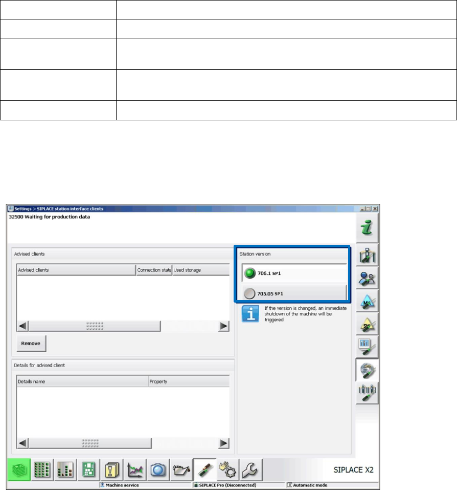
The compatible mode can be activated under Settings – SIPLACE station interface clients on
the GUI.
Figure 7-28: Setting compatible mode
Station Software 7xx to 714.0 (R20-2) / Feature Description 11/2020 Edition
93
7.28 SIPLACE X-Series S – X3 S, X4 S, X4i S Placement Machines
Compatible mode: Not supported
The station software supports the X3 S (with three gantries), X4 S and X4i S (with four gantries)
placement machines of the new SIPLACE X-series S. The X4i S resembles the X4i and the X4 S
resembles the X4 placement machine. The only difference between the X3 S and the X4 S
placement machines is that gantry 2 fails for the X3 S and consequently, it resembles an X3
placement machine.
For the X4i S it is necessary to define the table position (inner and outer) in the Auto Configuration.
For the X3 S and X4 S, only the outer table position is supported.
To minimize the distance between feeder and conveyor, the small calibration tool holder with a
small calibration tool device is used for the CPP placement head. However, if a stationary camera
is used simultaneously, the big calibration tool device with the corresponding calibration tool holder
still must be used.
Smart Pin Support is supported. Each gantry must be equipped with a pin picker if Smart Pin
Support is used.
The new conveyor system for the SIPLACE X-series S is supported.
7.29 New Conveyor System for SIPLACE X-Series S
Compatible mode: Not supported
A new conveyor system has been introduced for the SIPLACE X-series S placement machines.
The conveyor system consists of five sections: input section, processing section 1, intermediate
section, processing section 2, output section and supports single and dual conveyor lane mode.