SIPLACE Station Software 7xx to 714 介绍.pdf - 第191页
Station Software 7xx to 714.0 (R20-2) / Feature Description 11/2020 Edition 191 Features (V709.1 : Compatible Mode 708.2) 10.11 SIPLACE TX -Series – Enhancements Compatible mode: Not supporte d 10.11.1 Reject Plate Suppo…
Station Software 7xx to 714.0 (R20-2) / Feature Description 11/2020 Edition
190
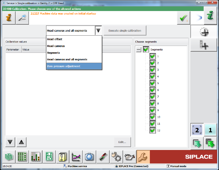
– The Single calibration view has been redesigned as follows:
Figure 10-14: Single calibration view
The new view is separated into one part for the calibration results and one part for segment
selection. If no selection is necessary, the table will be expanded to full size. Every calibration
step displays the results in an individual table. A calibration step can be selected in the combo
box and executed by pressing the Execute single calibration button.
SIPLACE Vision is active only while executing the calibration. The images of the camera are
displayed in a detailed result window.
Station Software 7xx to 714.0 (R20-2) / Feature Description 11/2020 Edition
191
Features (V709.1: Compatible Mode 708.2)
10.11 SIPLACE TX-Series – Enhancements
Compatible mode: Not supported
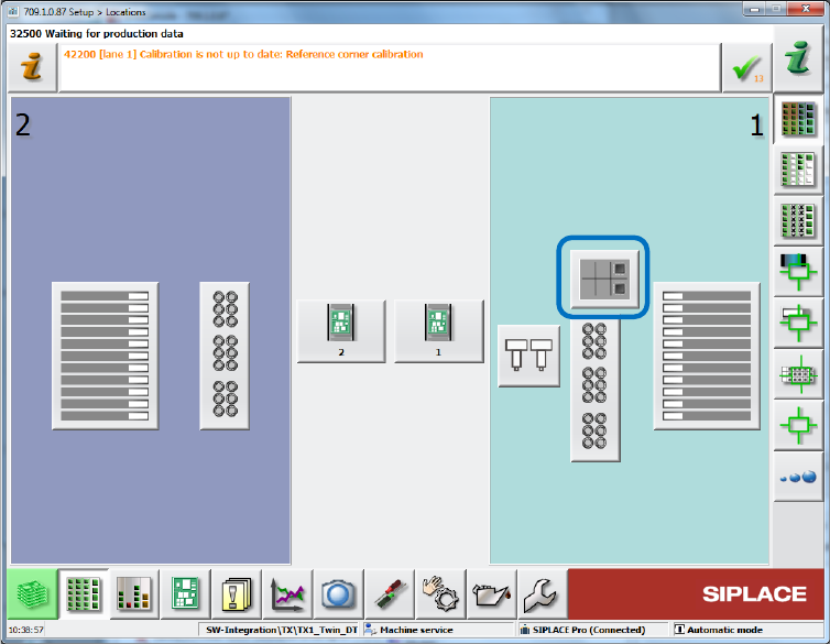
10.11.1 Reject Plate Supported on GUI
The reject plate is a fixed mounted plate on which the station can drop rejected components after
the SIPLACE Vision system detected errors. If a reject plate is installed in a SIPLACE TX
placement machine, a corresponding button will be displayed in the main menu of the station
software. This option must be enabled in SIPLACE Pro for the respective component / component
shape.
Figure 10-15: Reject plate in main menu
Station Software 7xx to 714.0 (R20-2) / Feature Description 11/2020 Edition
192
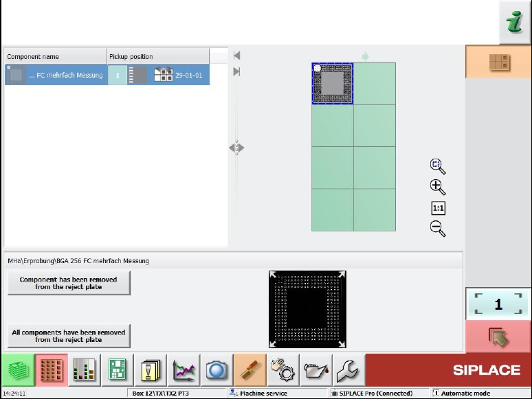
By selecting the reject plate button, the following dialog box opens:
Figure 10-16: Rejected components on the reject plate
This dialog box contains a list of the components put onto the reject plate and a graphical
representation (grid) of the plate with the components on it. A component can be selected from the
list or in the grid, the selection is automatically synchronized.
Additionally, the pickup position from where the component was picked up is displayed. If a
component was picked up from a tray, only the level and magazine number are displayed, not the
pickup position in the magazine!
Once a component has been selected, the attached Vision dump is displayed (if still existing on the
drive).
With this information the operator can check whether the component is ok or not and decide to put
it back in the feeder again. This requires that the feeder from which the component was picked up
is still inserted in the machine at the same location.
The operator can confirm the removal of the component from the reject plate with the Component
has been removed from reject plate button. Confirmation must be done for each component.
A multiple selection is not available.
10.11.2 Increased Component Range for Twin Head
Until now, the component range for Twin Head on SIPLACE TX-series placement machines was
limited to 55 x 45 mm due to the reject bin size. To allow larger connectors to be placed, the
component range has been increased to 75 x 10 mm from this station software version. For this,
the nozzle reject bin must be removed from the side on which the Twin Head is mounted. If the
components are correspondingly marked in SIPLACE Pro, they will be rejected onto the reject
plate.