SIPLACE Station Software 7xx to 714 介绍.pdf - 第154页
Station Software 7xx to 714.0 (R20-2) / Feature Description 11/2020 Edition 154 Figure 9-3: Measured height The pickup of the component with t he new measured height can be repeated via the Pickup component button. If ne…
Station Software 7xx to 714.0 (R20-2) / Feature Description 11/2020 Edition
153
9.6 Measuring and Changing the Component Height
Compatible mode: Not supported
Inaccurate component height definitions may cause unnecessarily high reject rates. This shall be
prevented by measuring the height exactly with the component sensor and transmitting it to
SIPLACE Pro and/or adding it into the Component Shape Editor in SIPLACE Pro.
As of this station software version, the operator can test the component height at the station during
pickup. The placement head must be equipped with a component sensor and the nozzle /
component combination suitable for performing such a measurement.
If necessary, the operator can change the component height and upload it to SIPLACE Pro as of
the Advanced production activity level.
If SIPLACE Pro security is enabled, the operator logs on to SIPLACE Pro with a user account after
having downloaded a recipe. This user account must have write permission for the component
shape in the SIPLACE Pro database and also permission to upload objects to SIPLACE Pro.
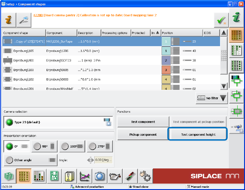
Figure 9-2: Testing the component height
If the new Test component height button is selected when the component shape is taught in the
station software, a new dialog box is opened in which the height measured by the component
sensor is displayed.
Station Software 7xx to 714.0 (R20-2) / Feature Description 11/2020 Edition
154
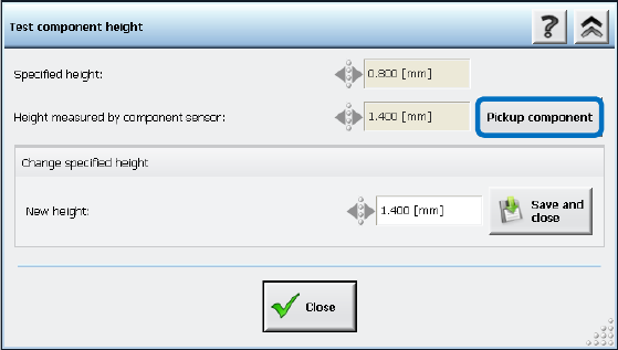
Figure 9-3: Measured height
The pickup of the component with the new measured height can be repeated via the Pickup
component button. If necessary, the measured value can be changed and uploaded to SIPLACE
Pro. The component shape will be updated accordingly in SIPLACE Pro by SIPLACE Pro Line
Control.
Restrictions
– Only for nozzle and component combinations in which the component height is supposed to be
measured with the component sensor.
– The component sensor will not perform any measurement if the component height
measurement is omitted due to SIPLACE Pro rules.
9.7 Logging from Subsystems – Enhancements
Compatible mode: Complete
9.7.1 E Logbook
With the E logbook mechanism (Electronic Card Logging), serial numbers are read from a
subsystem and stored in the ECardLog.xml file. The serial numbers of new modules are listed
under "CurrentMachine" and the old serial numbers of exchanged modules under
"MachineHistory". Thus, the exchange of modules in a machine can be easily detected.
In this station software version, the already available E logbook has been enhanced to include the
recorded data from the following subsystems:
● Complete placement head (with serial number KL-…)
● HCU
● Sensor modules (X, Y)
● FCU
● CAN card
● Box PC
● Power supply (pulse)
Station Software 7xx to 714.0 (R20-2) / Feature Description 11/2020 Edition
155
9.7.2 Statistics Data
The statistics data for the dp-axes of the C&P20A placement heads is read from the subsystem
and stored in the CP20DPDump.xml file. As of this station software version, the statistics data is
additionally recorded for the following subsystems in the same way:
● C&P20 P pressure control valve
● CPP star axis
● CPP z-axis
In contrast to the statistics data for the dp-axes of the C&P20A placement heads that is only
updated during the machine start, the additional statistics data is cyclically loaded from the
subsystems every 24 hours. The data is stored in the C:\Sirio\Work\eSW folder. A separate file is
created for each subsystem.
9.8 New State for Segments of C&P Placement Heads
Compatible mode: Complete
If placement quality and pickup problems occur, the operator frequently disables segments of C&P
placement heads what often results in exchanging the module. However, in many cases the
module is not defective, but the problem was caused by a worn nozzle or filter disk.
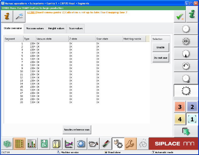
In such cases, the new Do not use state can be set for the head segments in the Manual
operations in the State overview view. The Not used state is assigned to the respective
segment. Defective segments first must be set to Do not use and additionally disabled via the
Disable button. Via the Enable button, the segment can be put into operation again.
Figure 9-4: Setting the state for segments