SIPLACE Station Software 7xx to 714 介绍.pdf - 第247页
Station Software 7xx to 714.0 (R20-2) / Feature Description 11/2020 Edition 247 Information on the MeasuringFeede r X, such as counter values a nd feeder ID can be access ed under Manual Operations . The counter s are us…

Station Software 7xx to 714.0 (R20-2) / Feature Description 11/2020 Edition
246
– Free garages are needed
The operator will see how many and where the free garages are needed. There are two
possible solutions: either the pins are removed manually from the garages or free garages are
made available by inserting a pin feeder.
– Support pins are needed
The operator will see how many and where the support pins are needed. There are two
possible solutions: either the pins are inserted manually in the garages or support pins are
made available by inserting a pin feeder.
In the Preventive Maintenance view, all pins can be removed automatically from the lifting table
by clicking the button Prepare for manual maintenance.
13.5.2 Prompt To Fill Or Empty Magazines / Garages
Whenever necessary, a detailed error will be displayed prompting the operator to fill or empty the
magazines / garages. This applies to all pin magazines (W5, Q10, L10 and T5) on all placement
machines series using Smart Pin Support.
13.6 Linear Dipping Unit 2 X / Linear Dipping Unit E – Enhancements
Compatible mode: Hidden
From this station software version, multiple cavity depths (max. five) can be used on the same
dipping plate. Optionally, the dip module can be equipped with a flux level sensor.
Detailed information on the functionality of the Linear Dipping Unit 2 X and Linear Dipping Unit E
can be found in the respective User Manuals SIPLACE Linear Dipping Unit 2 X, item no.
[00198517-xx] and SIPLACE Linear Dipping Unit E, item no. [00198521].
13.7 Shuttle Extension for SIPLACE SX V2-Series
Compatible mode: Hidden
The Shuttle Extension for SIPLACE TX-series is also supported for the SIPLACE SX V2-series
placement machines.
13.8 SIPLACE MeasuringFeeder X
Compatible mode: Hidden
The station software supports the new SIPLACE MeasuringFeeder X with which the electrical
characteristics of a component can be measured. The respective attributes and additional
information such as treatment of used components must be specified in SIPLACE Pro.
The measurement will be performed at each detected component change, e.g. after a refill or splice
operation, a foil torn error, the first setup at the machine or a new feeder setup.
The MeasuringFeeder X must be set up manually and occupies one track on the X-table.
Components that were marked for measurement are automatically measured during production
following the rules that were defined during production planning.
NOTICE
The operator must ensure that the component is available for measurement!
Station Software 7xx to 714.0 (R20-2) / Feature Description 11/2020 Edition
247
Information on the MeasuringFeeder X, such as counter values and feeder ID can be accessed
under Manual Operations. The counters are used for wear evaluations of the contact module. A
button for a self-test is also offered. During the self-test, the internal wiring of the feeder and the
basic function of the measuring board are checked.
All measurements and options related to the measuring feeder are displayed in an own
Measurement unit setup view.
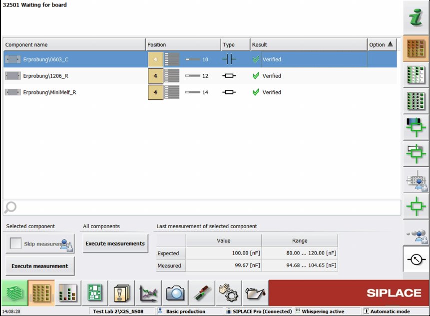
Figure 13-1: Setup view for MeasuringFeeder X
In this dialog, the state of the planned component measurements can be checked.
When a row in the list is selected, the expected value and tolerance range from the last
measurement are displayed. The expected value is always displayed, even if a measurement
failed.
If the measurement is out of tolerance, a detailed error is displayed and the respective track
disabled. The user can decide to execute a manual measurement for the selected component or to
skip the measurement. For skipping the measurement, the Advanced production activity level is
required.
The measured values of the reference component of one package will be recorded in the trace
data. Each subsequent component from the package has this information attached. If a
measurement failed, the result will also be attached to the package, even if no component will be
picked up afterwards.
By clicking the Generate report button, a report of the measured components is generated in an
HTML file. The report contains the measured value and the expected value of the components and
the feeder ID.
Detailed information on the MeasuringFeeder X can be found in the SIPLACE Measurement
Feeder X User Manual, item no. [00198526-xx].
Station Software 7xx to 714.0 (R20-2) / Feature Description 11/2020 Edition
248
13.9 Station Behavior When Using Alternative Tracks
Compatible mode: Not supported
Alternative track means that one or more feeders are set up with the same component on a feeder
table. Alternative tracks are mainly used to avoid machine stoppages caused by pickup issues on
the main track, e.g. foil torn, late splicing.
To avoid half empty reels or the mixing of components from different reels on the board, the user
can select when the machine shall switch between main and alternative track.
A new option has been introduced to control the behavior of the station if a feeder can no longer
deliver a component, but the track did not run empty. The user can select the behavior for each
component.
Alternative tracks are only supported together with ASM Setup Center.
13.10 "Cracked Die Inspection"
Compatible mode: Not supported
Cracked components can be detected with the new "Cracked Die Inspection". This option is
supported for the following component shapes:
BAREDIE
BGA
CCGA
CHIP
Non-standard
If the "Cracked Die inspection" is enabled in SIPLACE Pro, the components will be measured
with the board camera. If the component is cracked, it will be left in the tray or tape.
At the station, the inspection can be started under Setup – Component shapes – Actions –
Perform "Cracked Die inspection".