SIPLACE Station Software 7xx to 714 介绍.pdf - 第165页
Station Software 7xx to 714.0 (R20-2) / Feature Description 11/2020 Edition 165 Prerequisites – All stations in the line m ust be equipped with the sam e station software (version 708.1 or higher). – WDTL must be provide…
Station Software 7xx to 714.0 (R20-2) / Feature Description 11/2020 Edition
164
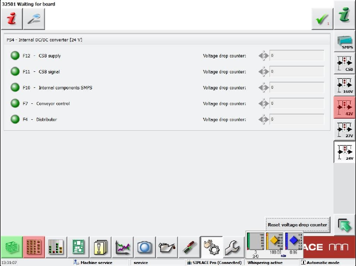
If a fuse group is selected (here 24V), a corresponding view is displayed.
Figure 9-11: Fuse group view
The states of the assigned fuses are displayed in the following colors:
Gray: switched off
Green: switched on
Red: faulty
One long name and one short name are displayed for each fuse. The short names are the same as
those in the figures of the real hardware that can be found in the Online help of the station
software.
Additionally, the number of voltage drops since the last reset is displayed. The counter for all
displayed fuses can be reset with the Reset voltage drop counter button.
9.19 WDTL – Multiple Set-up Components in Barcode Controlled
Production with Synchronous Dual Lane Mode
Compatible mode: Not supported
The station software now supports multiple set-up components in barcode-controlled production
with synchronous dual lane mode. Multiple set-up components mean that the components are set-
up on more than one station.
In synchronous dual lane mode, each of the two boards gets the same unique ID for the SIPLACE
Pro job in the first station. This ID will be transferred by WDTL through the line.
If boards with the same ID are moved together into another station, the boards will be placed
together with the same SIPLACE Pro job. This is the usual case.
If boards with different IDs are moved together into another station, the boards will be separated
and separately placed in asynchronous mode.

Station Software 7xx to 714.0 (R20-2) / Feature Description 11/2020 Edition
165
Prerequisites
– All stations in the line must be equipped with the same station software (version 708.1 or
higher).
– WDTL must be provided through the complete line. If a SIPLACE cluster is interrupted by a
device like an AOI system, WDTL is only possible via individual PCB barcodes.
9.20 "Feeding on Demand" Option for Tape Feeders
Compatible mode: Complete
As of this station software version, the Feeding on Demand option can be used for all tape
feeders. With this option it can be avoided that components remain in the tape without a cover foil
and fall out at a changeover.
The option is set in the SetupUnitTypes.xml configuration file and oriented either to the head cycle
or the board cycle dependent on the feeder type. For fast feeders like the 8 mm and 2x8 mm
X-feeders, the head cycle variant is used.
The board cycle variant can be enabled per station. Only one sequence for each feeder type can
be set and a mixture is not supported.
NOTICE
Components without a cover foil can possibly remain in the tape if a board is canceled,
i.e. if it has not been completely placed.
9.21 Configurable "Pickup Components during Measuring Fiducials"
Compatible mode: Not supported
Previously it was standard that the components were already picked up and measured while the
board entered the machine for a faster passing through. This practice was only suppressed if ink
spots had to be evaluated.
Now it can be configured in SIPLACE Pro if pre-pickup shall be performed always, never or
dependent of the recipe.
The option can only be overridden by correcting the configuration files of the station software
respectively. However, this should only be performed for test and integration purposes.

Station Software 7xx to 714.0 (R20-2) / Feature Description 11/2020 Edition
166
9.22 Placement of Components 03015 / 0201 with C&P20 A or C&P20 P
Compatible mode: Not supported
The component shapes that can be selected in SIPLACE Pro for the placement process are based
on the imperial units, i.e. on inches (1 inch = 2.4 cm) with one exception: component shape 03015
is based on the metric system.
As of this station software version, a new metric-based component shape 0201 can be defined in
addition to the existing, inch-based component shape 0201.
For the metric-based component shape0201, a new nozzle type has been introduced that is
supported by the C&P20 A and C&P20 P placement heads. The nozzle number 1002 is assigned
to the C&P20 A placement head and 4102 to the C&P20 P placement head.
NOTICE
Selection of the component shapes in SIPLACE Pro
In SIPLACE Pro, the component shapes 0201 (= inch-based) or 03015m
(= metric-based) can be selected for the placement process.
SIPLACE Pro treats the metric-based component shapes 0201 as component shapes
03015m. Therefore, in this case 03015m has to be selected and not 0201!
9.23 Optional Automatic Detection of the Feeder Pitch
Compatible mode: Complete
Components in tapes are often delivered with different feeder pitches dependent on the
manufacturer. In this case, the operator must adapt the pitch manually what might cause a big loss
of components from a tape reel if the setting is incorrect.
For this, the already available Automatic feeder pitch detection function (see section 5.7) has
been enhanced. As of station software version 708.1, an optional automatic feeder pitch detection
can be set and performed during runtime.
The automatic feeder pitch detection can currently solely be performed for 8 mm and 2x8 mm
X-feeders.
Prerequisite
The operator must be authorized to download from and upload to SIPLACE Pro, see
section 7.38.