SIPLACE Station Software 7xx to 714 介绍.pdf - 第260页
Station Software 7xx to 714.0 (R20-2) / Feature Description 11/2020 Edition 260 Features (V712.1 (R19 -1): Compatible Mode 711. 2) 13.17 OSC Packa ge Option – Enhancements Detailed information on the OS C Package feature…
Station Software 7xx to 714.0 (R20-2) / Feature Description 11/2020 Edition
259
– For tape feeders:
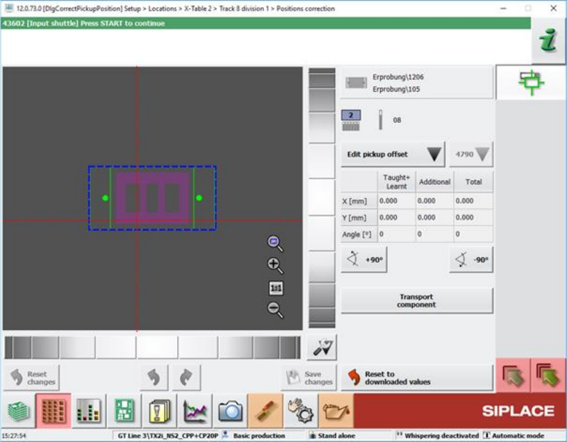
The nominal pickup position is displayed as red and dotted crosshairs in the Positions
correction teaching dialog and the Check tape position at pickup position of track machine
function dialog.
Figure 13-9: Positions correction teaching dialog
The pickup position is determined by the current Pickup position feeder setting and the
Fiducial measurement result which may be zero if neither fiducial nor pocket recognition are
specified.
Compatible mode: Complete
– Optimized selection controls for the touch screen.
The selection of a tray inside an MTC, WPC or generic automatic tray (i.e. JTF) widget can be
done by zooming in when the user touches the widget.
Compatible mode: Complete
– Windows 10 can be used for station computers on SIPLACE SX V2 placement machines.
Station Software 7xx to 714.0 (R20-2) / Feature Description 11/2020 Edition
260
Features (V712.1 (R19-1): Compatible Mode 711.2)
13.17 OSC Package Option – Enhancements
Detailed information on the OSC Package features can be found in the OSC Package User Guide,
item no. [00198374-xx].
The main enhancements made for the OSC Package Option in the station software and SIPLACE
Vision are listed in the overview below.
Height Values for Snap-In and Pin-In-Paste Components Saved Machine-Dependently
Compatible mode: Complete
When restarting a machine, the height teaching step for snap-in / pin-in-paste components does
not need to be repeated. However, the height teaching step still needs to be repeated if attributes
of the board have been changed in SIPLACE Pro.
Placement of Critically Tall Components with Twin VHF or CPP Placement Head
Compatible mode: Hidden
It is possible to place several critically tall components. The collision typology model has been
extended to support this new feature.
The target head for critically tall components is either a CPP head in high head position or a Twin
VHF head. Which components are considered critically tall depends on the respective placement
head they are placed with.
Chipping Inspection
The component chipping detection functionality checks whether the edge of a component has
larger deviations than defined. It can be enabled or disabled using the Chipping inspection
checkbox in the Vision Inspection tab of the Component Shape Editor of SIPLACE Pro Desk.
Restrictions
– Only supported for vision types BareDie, BGA, CCGA, Chip, Moulded, Nonstandard.
– The OSC license must be available.
13.18 Robustness Package – Enhancements
Automatic Checking for Camera Soiling
Compatible mode: Complete
In Maintenance > Verification, the option Check for camera soiling has been added which can
be used to perform a check for soiled cameras.
When an illumination calibration is performed, the system will do an automatic checking for camera
soiling. If this is not desired, the automatic checking for camera soiling during an illumination
calibration can be turned off with the new option Skip check for soiling of all cameras in
Maintenance > Verification > Calibrate illumination.
Restrictions
– The check for camera soiling is implemented for the camera types SST23, 28, 29, 30, 38, 41,
45, 46, 48 and 49.
Station Software 7xx to 714.0 (R20-2) / Feature Description 11/2020 Edition
261
Changed Behavior for Errors on Alternative Components
Compatible mode: Complete
The needed operator actions for when a vision error occurs concerning alternative components has
been reduced.
Detection of Protruding Empty Tape
Compatible mode: Complete
It is possible that empty component tapes do not enter the tape channel which may cause head
crashes if not detected. To prevent this, special structures on the track ruler are measured to detect
any tapes not entering the tape channel.
Restrictions
– Component tapes not entering the tape channel can only be detected after some time has
passed during production. For the detection it is necessary that the fiducials are always within
the PCB camera field of view.
– The inspection can only be carried out on machines on which the track ruler has fiducial
structures (cross-shaped fiducials) printed on it.
Using Individual Pickup Error Thresholds for Components
Compatible mode: Hidden
The station software issues warning and error messages when pickup errors occur (including vision
errors). These warning and error messages are triggered by threshold values, which, by default,
are identical for all tracks. However, as of SIPLACE Pro 16.1 it is possible to configure these
threshold values individually in SIPLACE Pro, overruling the default values from the station
software.
The station software adopts the individual threshold values from SIPLACE Pro. If no individual
threshold values are specified, the default values from the setup configuration are used.
13.19 "IPC-HERMES-9852" – Enhancements
Compatible mode: Complete
The following enhancements have been made in the implementation of the "IPC-HERMES-9852"
protocol for Hermes 1.1 for the placement machines:
Whispering of IPC-HERMES-9852 Data
IPC-HERMES-9852 data can be whispered down a line even if a SIPLACE machine equipped with
“Advanced PCB interface”, i.e. a machine that does not support IPC-HERMES-9852, is part of the
line.
Barcode Controlled Production for Boards with Different Width
When IPC-HERMES-9852 is activated on a machine, this machine can use the board width
provided by IPC-HERMES-9852 data to adjust its conveyor rails accordingly. This way, barcode
controlled production is no longer limited to boards of equal width.
The Adjust width dialog under Setup > Conveyor has been extended to support this new feature.
Restrictions
– If the upstream machine does not provide a barcode with width information via
IPC-HERMES-9852, no width adjustment will be performed.