SIPLACE Station Software 7xx to 714 介绍.pdf - 第252页
Station Software 7xx to 714.0 (R20-2) / Feature Description 11/2020 Edition 252 13.13 Redesigned Cali bration View Compatible mode: Compatible For a better overview of t he calibration steps, the followin g new views rep…
Station Software 7xx to 714.0 (R20-2) / Feature Description 11/2020 Edition
251
13.11 Measuring Barcode on Bottom Side of Component
Compatible mode: Not supported
For a component it can be specified that its barcode on the bottom side shall be read with the
component camera and stored in the Traceability data. A corresponding barcode description must
have been defined in SIPLACE Pro. The barcode data is generally the same as for barcodes that
can be read by the board camera.
If the barcode could not be read, the component will be:
– rejected if it was picked up from a feeder
– returned to its pick location if it was picked up from a tray
– returned to reject conveyor or reject plate, if available
13.12 Pass-Through Mode for Boards without Recipe
Compatible mode: Compatible
If the Transport through conveyor mode is set for the conveyor, the recently used board length is
used when transporting the boards. The board length is mandatory for transporting a board without
a recipe. Usually, customer boards are used for setting up and testing a new line. These boards
may have another length than the test boards used before.
To avoid conveyor errors, the current board length can now be modified without being connected to
SIPLACE Pro. An editable field for the board length has been added to the Lane – Functions
dialog in the conveyor settings.
Restrictions
The feature is not supported for lines containing shuttles.
Station Software 7xx to 714.0 (R20-2) / Feature Description 11/2020 Edition
252
13.13 Redesigned Calibration View
Compatible mode: Compatible
For a better overview of the calibration steps, the following new views replace the current automatic
calibration dialog:
– Calibration state
– Automatic calibration
– Calibration scripts
After clicking the Automatic calibration button in the main service dialog, the views can be
accessed via the right toolbar.
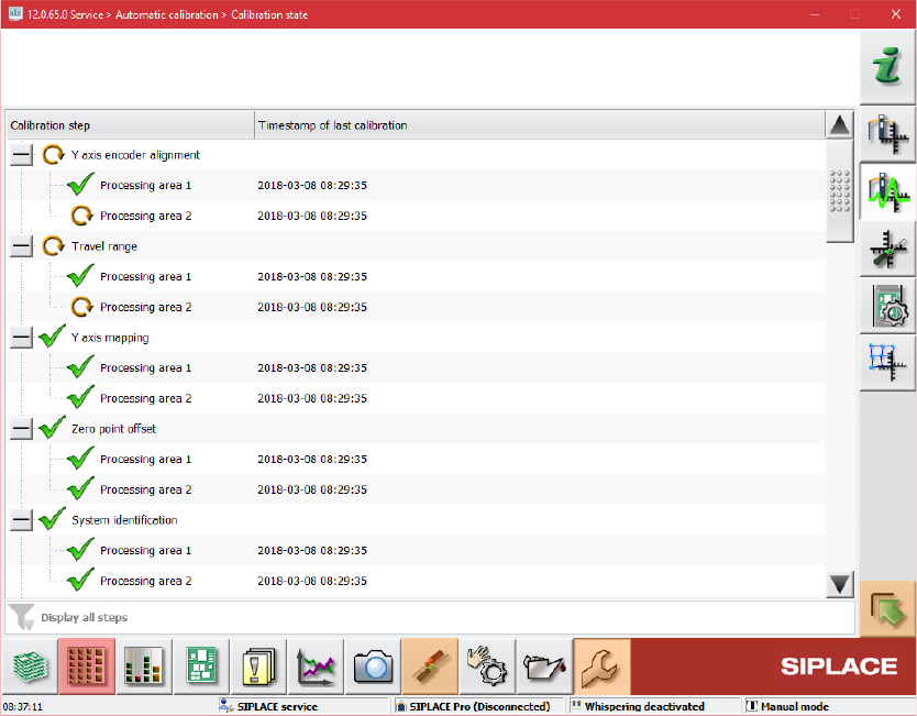
Calibration state overview
Figure 13-4: Calibration state overview
This view is introduced for displaying the state of the calibration items. A list with all calibration
items is displayed as a tree. The list is dynamic and is updated e.g. after an automatic calibration
run has been performed, during production or after single calibrations.
The following information is displayed:
– Name of the calibration item
– Timestamp of the last calibration
– State of the calibration (icon in front of the item name)
Station Software 7xx to 714.0 (R20-2) / Feature Description 11/2020 Edition
253
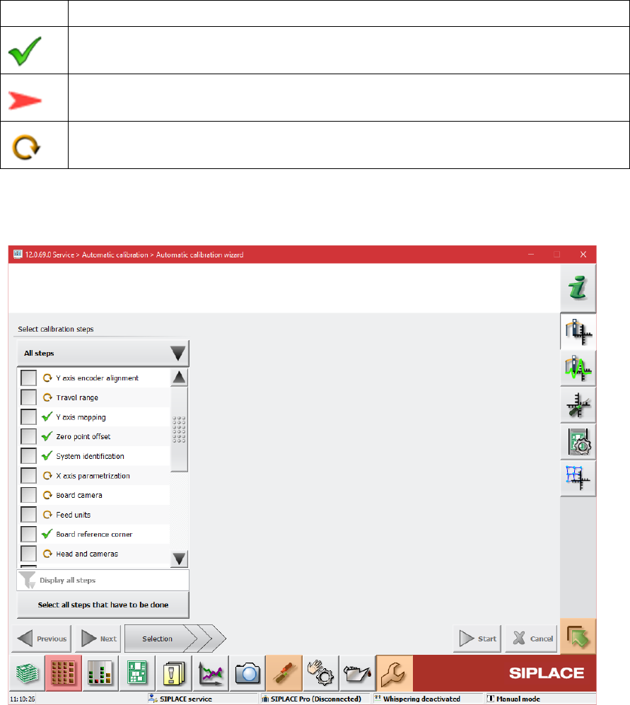
Explanation of the states
Icon
State
Calibration has been successfully performed
Calibration has not been performed
Calibration must be performed again because of a dependency to another calibration
item (i.e. if board mapping is executed, the head mapping should also be performed)
Automatic calibration wizard
Figure 13-5: Automatic calibration wizard
The second new view is intended for executing the calibration steps and consists of three pages.
The first page of the wizard lists the calibration steps and their states but no locations. The
contents of the list can be different depending on the user choice done through the button above
the list. The user choice will be stored. There are three possible choices:
– Combined steps: The offered steps are combined steps, they represent common tasks and
give a quick access to them.
– All steps: All calibration steps are in the list. The user can select every step to be executed.
– Single steps only: The steps that are not part of combined steps are displayed. Thus, the user
can quickly access steps like Bulkfeeder X, Vacuum tooling, etc.
There is no check if the user steps are compatible to each other and no automatic selecting of
other steps.