SIPLACE Station Software 7xx to 714 介绍.pdf - 第281页
Station Software 7xx to 714.0 (R20-2) / Feature Description 11/2020 Edition 281 Table 15 -1: Displayed error mess age if barcode information does n ot match recipe In the Hardware fiducials tab of the Current machine req…

Station Software 7xx to 714.0 (R20-2) / Feature Description 11/2020 Edition
280
15.8 Automatic Recognition of XX Nozzle Magazine Change on
Prepare for Production
Compatible mode: Complete
After restarting the station software, or after exchanging a nozzle magazine, the nozzle magazine
types are checked via the fiducials at the start of production and exchanged automatically, if
necessary. Afterwards, the garages of the magazine, or the nozzle contained in it, are scanned. If a
magazine was exchanged, the already measured height of the previous magazine is taken over, so
there is no need to calibrate again. If no height measurement value is available, then the magazine
must be calibrated once.
The function can be disabled with the Skip nozzle id scanning check box in the Check and set
software options - Machine configuration dialog.
Restrictions:
– The nozzle changer must be connected to XFCU (Feeder Control Unit for X-tables).
– This function is not supported for twin nozzle magazines.
– The magazines can only be automatically exchanged during production preparation before
nozzle type scanning and not during manual functions or the calibration of nozzle magazines.
– Each spot in the magazine must be fully calibrated at least once in order to use the automatic
nozzle magazine exchange. Please note that for the measurement of the z-height, a calibration
nozzle is necessary.
15.9 Verifying Clinching Tool by Barcode Fiducial
Compatible mode: Complete
NOTICE
Please contact ASM service if you want to activate this feature.
A Clinching tool consists of a plate with several beveled pins on top that is installed in a placement
machine. After placement of THT components (e.g. capacitors), this plate is pressed to the
underside of the PCB to clinch the leads of the THT components.
Whenever you use a clinching tool in a station, you need to configure it in the recipe in SIPLACE
Pro and in the station software. To verify that the correct clinching tool has been installed in the
station, the configuration on the station is compared with the specifications in the recipe. To
automatically identify the clinching tool installed in the station, a barcode fiducial can be used that
is placed on the clinching tool surface. The barcode contains information on the clinching tool, e.g.
its name and exact clinching tool type.
During recipe download, when the conveyor is empty, the clinching tool and the lifting table are
lifted to upper position, where the barcode on the tooling surface can be scanned by the PCB
camera. The information contained on the barcode is then compared to the specifications in the
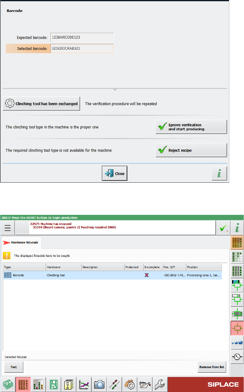
recipe. If the barcode cannot be read, if the clinching tool type is unknown, or if the information in
the barcode does not match the data stored in the station software configuration, a corresponding
detailed error message is displayed:
Station Software 7xx to 714.0 (R20-2) / Feature Description 11/2020 Edition
281
Table 15-1: Displayed error message if barcode information does not match recipe
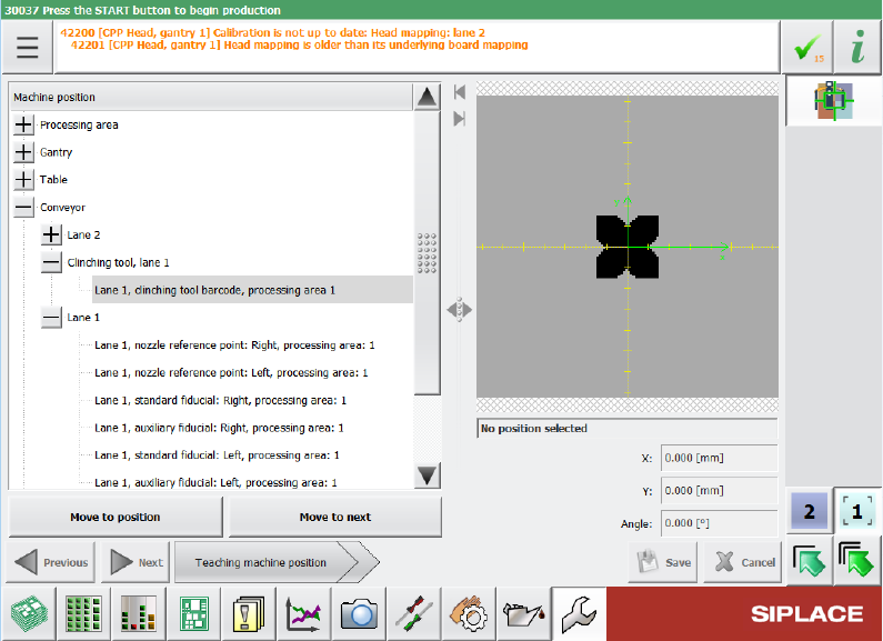
In the Hardware fiducials tab of the Current machine requests for teaching view in the station
GUI, you can view the barcodes for clinching tool that need to be taught.
Table 15-2: List of clinching tool barcodes that need to be taught
The barcode is also shown in the list of teachable machine positions, after it was saved once within
conveyor individual files. The position is teachable and can be changed.
Station Software 7xx to 714.0 (R20-2) / Feature Description 11/2020 Edition
282
Figure 15-3: Teaching clinching tool
Restrictions:
– Currently, only one clinching tool is supported at a time.
15.10 Navigating Between Related Vision Dump Files
Compatible mode: Complete
The Options for selected positions dialog allows to take additional images of the component
within the pick & place process for the selected placement position. The functionality of this dialog
has now been extended so that, if the Before pick up option and the Dump on error option are
selected at the same time, it is possible to navigate between the two corresponding Vision dump
files to see a component before and after pickup.
For this, all images that have been taken within the same pick & place process are marked
accordingly. You can see the markup in the Measured object column inside the list of saved
Vision dumps. If you select a Vision dump in this list, you can click the new View related dumps
button to open the Related dumps view to see all Vision dumps that have been taken in the same
pick & place process as the selected file. In this view, you can switch between the Vision dump files
showing the component before and after pickup.