SIPLACE Station Software 7xx to 714 介绍.pdf - 第93页
Station Software 7xx to 714.0 (R20-2) / Feature Description 11/2020 Edition 93 7.28 SIPLACE X-Series S – X3 S, X4 S, X4i S Plac ement Machines Compatible mode: Not supporte d The station software supp orts the X3 S (with…
Station Software 7xx to 714.0 (R20-2) / Feature Description 11/2020 Edition
92
Features (V706.1: Compatible Mode V705.05)
7.27 Compatible Mode
The 706.1 station software version can be used as Version 705© in compatible mode on placement
machines that do not run with the 706.x station software only. I.e., the compatible mode may be
used on an SX1/SX2 but not on an SX1/SX2 V2 placement machine.
This means that the new functions of the current version can be used in the compatible version as
far as possible.
The visibility and functionality of the new functions in compatible mode are explained in the
following table.
Compatible Mode
Meaning
Complete
Complete function support.
Compatible
The function is visible and executable at the station. However, new add-
ons in the station software or in the line products are not supported.
Hidden
The function is invisible/inactive, e.g. due to licensing or unsupported
SIPLACE Pro download/upload.
Not supported
The function is not supported, e.g. because of failing hardware.
Table 7-1: Visibility and functionality in compatible mode
The respective visibility/functionality in compatible mode is specified for the new features in the
sections 7.28 to 7.51.
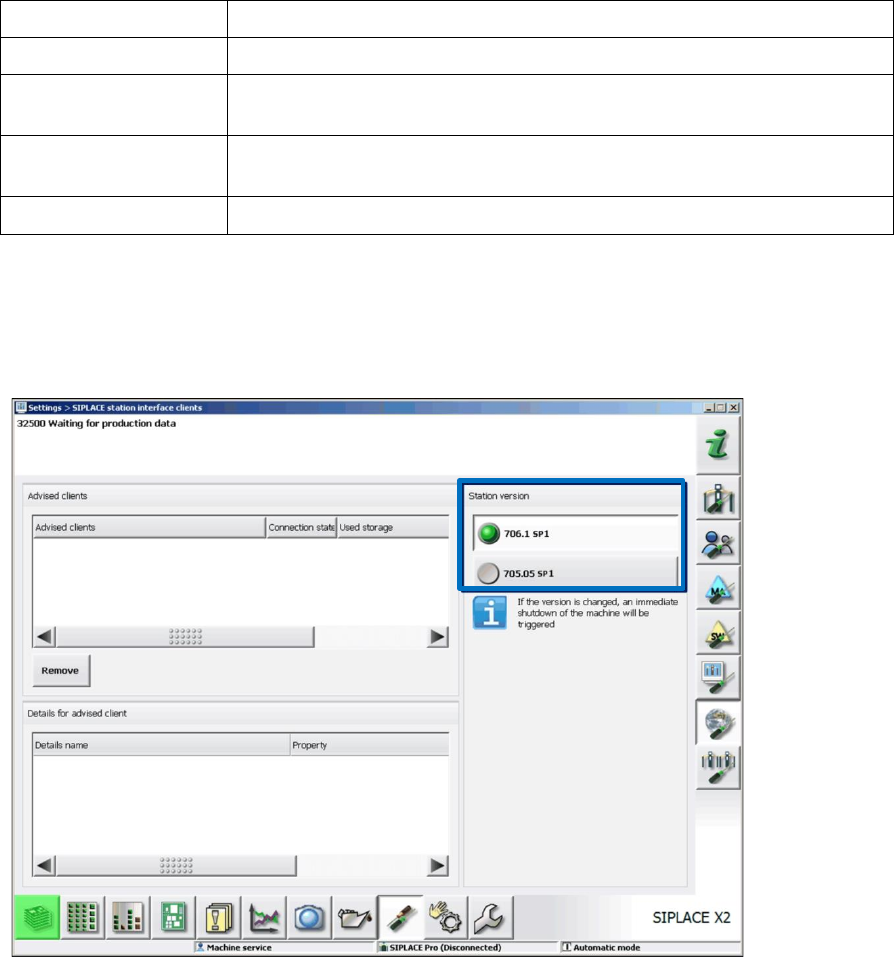
The compatible mode can be activated under Settings – SIPLACE station interface clients on
the GUI.
Figure 7-28: Setting compatible mode
Station Software 7xx to 714.0 (R20-2) / Feature Description 11/2020 Edition
93
7.28 SIPLACE X-Series S – X3 S, X4 S, X4i S Placement Machines
Compatible mode: Not supported
The station software supports the X3 S (with three gantries), X4 S and X4i S (with four gantries)
placement machines of the new SIPLACE X-series S. The X4i S resembles the X4i and the X4 S
resembles the X4 placement machine. The only difference between the X3 S and the X4 S
placement machines is that gantry 2 fails for the X3 S and consequently, it resembles an X3
placement machine.
For the X4i S it is necessary to define the table position (inner and outer) in the Auto Configuration.
For the X3 S and X4 S, only the outer table position is supported.
To minimize the distance between feeder and conveyor, the small calibration tool holder with a
small calibration tool device is used for the CPP placement head. However, if a stationary camera
is used simultaneously, the big calibration tool device with the corresponding calibration tool holder
still must be used.
Smart Pin Support is supported. Each gantry must be equipped with a pin picker if Smart Pin
Support is used.
The new conveyor system for the SIPLACE X-series S is supported.
7.29 New Conveyor System for SIPLACE X-Series S
Compatible mode: Not supported
A new conveyor system has been introduced for the SIPLACE X-series S placement machines.
The conveyor system consists of five sections: input section, processing section 1, intermediate
section, processing section 2, output section and supports single and dual conveyor lane mode.
Station Software 7xx to 714.0 (R20-2) / Feature Description 11/2020 Edition
94
The input and output sections are shorter than on previous SIPLACE conveyor systems and there
is no space to buffer boards in these sections. For this, the following solutions are possible:
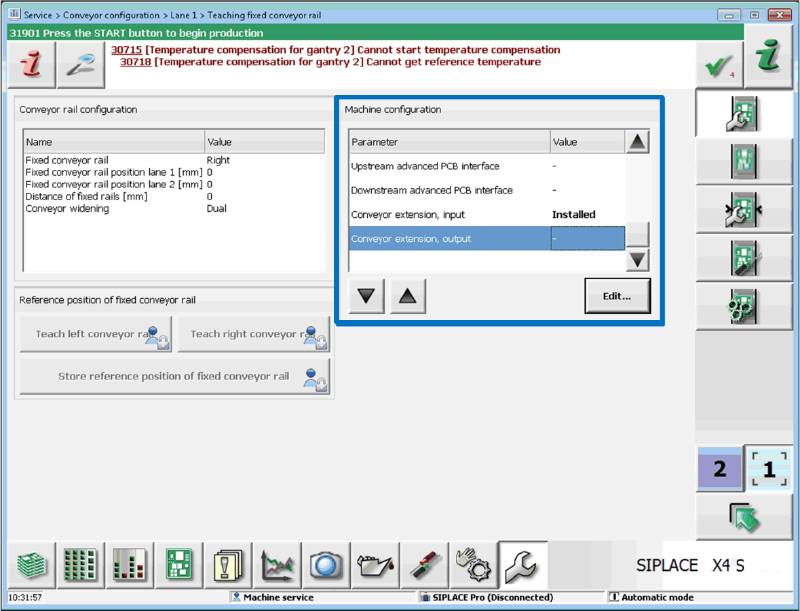
1. Input or output extensions can be optionally installed.
The behavior is then the same as for the SX4 conveyor system.
On the Machine Service activity level, the user must make the appropriate settings in the
hardware options, whether extensions are installed or not.
Figure 7-29: Setting pre-installed extensions
If necessary, the speed of the conveyor belts to hand over the boards from one machine to the
next one must be modified (under Conveyor speed parameters).
2. Using an overlapping buffer (possible for X3 S, X4 S and X4i S placement machines only).
If the placement machines stand in a line the input and output sections of both machines can
be used together as a buffer for a standard board.
For this, the new SIPLACE Interface must be installed (i.e., installing the corresponding cable).
A board that lies in the buffer area between two placement machines is displayed on the GUI in
the succeeding machine only.
3. Further line equipment (oven) can be installed behind the X3 S, X4 S or X4i S placement
machines.
In this case the board is treated like a long board. I.e., when the board enters the machine or is
moved to the output section, it occupies the placement area.
Belts in front of the placement machine do not have any special effect except that the board
does not enter the machine until the placement area is cleared.
In single conveyor lane mode there is one fixed and one flexible rail. The fixed rail can be installed
at different positions. In dual conveyor lane mode, all four rails are flexible, variable fixed rail
positions are possible.
The maximum board length is 450 mm without the Long Board option. The maximum board width
results from the fixed rail position and the conveyor mode (dual or dual as single). The maximum
board thickness is 6.5mm with the Thick Board option.