SIPLACE Station Software 7xx to 714 介绍.pdf - 第214页
Station Software 7xx to 714.0 (R20-2) / Feature Description 11/2020 Edition 214 11.2 Shuttle Extension for SIPLACE TX-Series Compatible mode: Not supporte d To reach the best possible output, shuttles might be required i…
Station Software 7xx to 714.0 (R20-2) / Feature Description 11/2020 Edition
213
11 Feature Description – Station Software V710.x
Features (V710.0 (R16-2): Compatible Mode 709.2)
11.1 SIPLACE TX micron – New Placement Machine
Compatible mode: Not supported
The new SIPLACE TX micron placement machine supports high precision placement on a dual
lane conveyor system. The placement machine exists in two variants: TX2 micron and TX2i
micron. The C&P20 M2 and CPP placement heads and the SIPLACE JTF-ML feeder are
supported. There are two X fiducial bars. A special vacuum tooling is optionally used to meet the
highest accuracy requirements. Along with the vacuum tooling, two Y fiducial bars are provided.
X fiducial bars are structured by crosses, point matrices and mini MAC structures that are used by
a new measuring procedure. The procedure offers features to increase the accuracy and make the
placement results long time stable. New calibration steps will be automatically performed, amongst
others for computing the head offset and recalibrating the gantry shape.
The precision capabilities of the station are defined in the new Accuracy Procedures XML table.
Please also refer to section 11.3.
11.1.1 Vacuum Tooling
A special vacuum tooling must be installed per conveyor lane for high precision placement with
15µm on the SIPLACE TX micron. The exact dimension of the vacuum tooling and the positions of
the fiducials are customer specific. The operator must select the vacuum tooling manually from a
list during the auto configuration.
The fiducials of the vacuum tooling will be measured in a measuring machine and the results
stored in a file. Every vacuum tooling entity is identified by a unique identifier that is contained in
the file. This file can be imported to the station and the data assigned to the related vacuum tooling.
The vacuum tooling must be removed during mapping. After mapping, it must be mounted and
calibrated again. The corresponding calibration step determines the current position (offset and
rotation) of the vacuum tooling in the machine during the automatic calibration.
If a vacuum tooling is installed, the following actions on the conveyor are not allowed:
– Adjusting a new rail configuration
– Moving a mapping board
11.1.2 ACT – Dependent on Precision
Compatible mode: Not supported
Placement machines like the SIPLACE TX, TX micron, CA4, CA4 eWLP, X4 S micron support
different classes of precision. To perform an ACT measurement for a specific accuracy new
SIPLACE Pro programs are available at the Download Center.
Dependent on the precision specified for a component shape in SIPLACE Pro, the appropriate
precision class will be selected for the ACT measurements. If there is no specific precision defined
the same algorithm as today will be used for selecting the used precision.
Station Software 7xx to 714.0 (R20-2) / Feature Description 11/2020 Edition
214
11.2 Shuttle Extension for SIPLACE TX-Series
Compatible mode: Not supported
To reach the best possible output, shuttles might be required in the SIPLACE line, e.g. when
I-Placement mode is used. For this, the new Shuttle Extension has been introduced for the
SIPLACE TX-series. One machine can have up to two shuttle extensions attached – one input
shuttle and one output shuttle.
The shuttle extension itself and its lane settings has to be configured in SIPLACE Pro. At the
station, the shuttle extension can be selected and configured as described in the following.
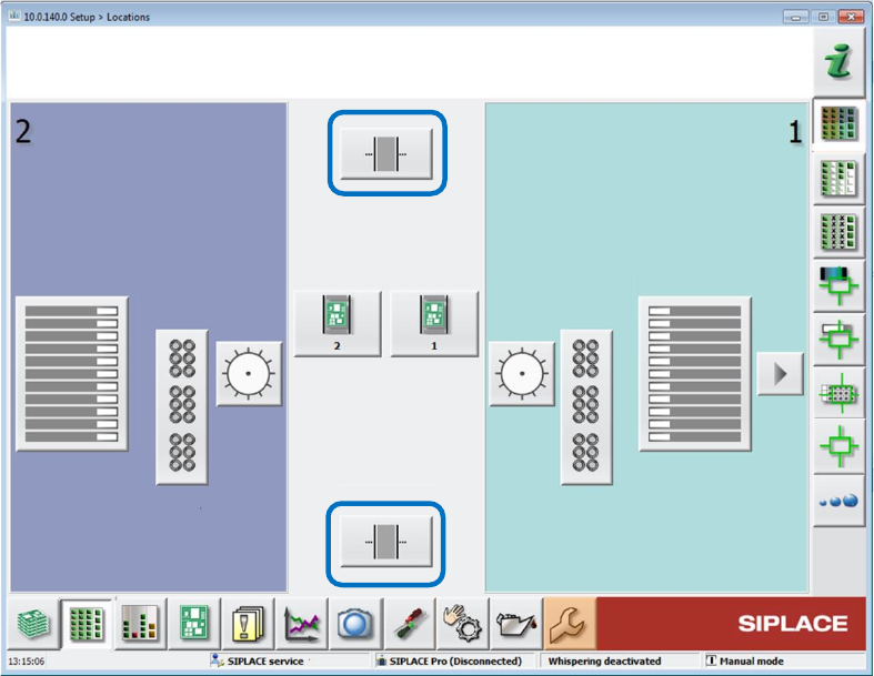
On the station, the Setup view has been extended by an additional button per shuttle extension.
Figure 11-1: Setup with shuttle extensions
The Manual operations subsystems dialog has been extended by a Manual operations shuttle
button for each shuttle extension.
The subsequent Manual operations dialog for the shuttle extension offers the following sections:
Current position / Align shuttle to
Transport width
Signals
Transport board to
Single functions are only available if the shuttle extension is not in automatic mode.
The Service tool has been extended by a Shuttle configuration button. The operator can
configure speed parameters, eSW parameters and single drives in the subsequent configuration
dialogs.
The Single calibration dialog has been extended by one button per shuttle extension.
The shuttle lane width has to be calibrated.
The alignment of the fixed conveyor rails of all lanes adjacent to the shuttle has to be calibrated.
When a lane is selected, the shuttle aligns itself to the chosen lane. The operator can then move
the shuttle in small or big steps to align the fixed rail and save the setting.
Station Software 7xx to 714.0 (R20-2) / Feature Description 11/2020 Edition
215
Restrictions
Barcode mode and station-wise download are not supported.
Detailed information on the shuttle extension can be found in the Shuttle Extension Assembly
Instructions and User Manual, item no. [00198271-xx].
11.3 Precision Value
The desired precision value for the component shape must be specified in SIPLACE Pro. If an
accuracy < 20 µm has been specified, the Micron 15u3Sigma – Machine Connection license is
required at the station.
11.4 Alternative Component Shapes
Compatible mode: Not supported
As of this station software version, alternative component shapes are supported. With this feature,
multiple component shapes can be assigned to one component. An own placement offset can be
assigned to each alternative component shape. An own feeder with pickup offsets (X and Y) and
pickup angle can be assigned to each alternative component shape.
Alternative component shapes must be specified in SIPLACE Pro.
The alternative component shapes process largely independently recognizes which component
shape description is to be used for the measurement. For each component, the SIPLACE Pro user
can select which method is to be used to select the used alternative component shape. Three
selection methods are available:
– Setup Center
The operator verifies the used component shape at the station. For this, ASM Setup Center
transmits additional attributes (e.g. the manufacturer component name) from the barcode label
of the packaging unit reel to the station. This attribute is used to select the appropriate
component shape.
– Station
SIPLACE Vision measures the component at the station and recognizes the used component
shape.
– Operator
The operator at the station determines, selects and confirms the used component shape on the
station software GUI.
Detailed information can be found in the Alternative Component Shapes User Manual,
item no. [00198270-xx].