SIPLACE Station Software 7xx to 714 介绍.pdf - 第264页
Station Software 7xx to 714.0 (R20-2) / Feature Description 11/2020 Edition 264 Restrictions – This functionality is onl y available for the nozzle ma gazines 6xxx(20), item no. [03218226 - xx] for the C&P20 P2 head …
Station Software 7xx to 714.0 (R20-2) / Feature Description 11/2020 Edition
263
14 Feature Description – Station Software V713.x
Features (V713.0 (R19-2): Compatible Mode 712.2)
14.1 Smart Pin Support for TX V2 – Enhancements
The Smart Pin Support for the TX V2 has been enhanced by the functions described below.
Using Partly Accessible Nozzle Magazines
Compatible mode: Complete
A new nozzle magazine with 20 garages has been introduced for the CPP head and C&P20 P / P2
head each:
– Nozzle magazine for CPP head: 20xx magazine, item no. [03135469-xx]
– Nozzle magazine for C&P20 P / P2 head: 40xx magazine, item no. [03218226-xx]
If the TX V2 is configured with Smart Pin Support, not all garages in these nozzle magazines can
be reached by the placement head. To avoid the entire nozzle magazine from being blocked, only
the garages out of reach are blocked and marked as such. All reachable garages can be used.
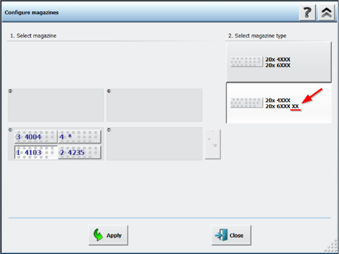
Nozzle magazines that are only partially reachable are marked with an additional “XX” behind the
magazine type name in the Configure magazines dialog.
Figure 14-1: Partly reachable nozzle magazine in Configure magazines dialog
Station Software 7xx to 714.0 (R20-2) / Feature Description 11/2020 Edition
264
Restrictions
– This functionality is only available for the nozzle magazines 6xxx(20), item no. [03218226-xx]
for the C&P20 P2 head and 20xx(20), item no. [03226630-xx] for the CPP head.
– At least two fiducials of partly reachable nozzle magazines must be in reach of the PCB
camera on the placement head.
– All nozzles that are in reach of the placement head must also be in reach of the PCB camera
on the placement head in order to scan the nozzle IDs.
Combination of Smart Pin Support with TwinHead on TX V2
Compatible mode: Complete
The combination of Smart Pin Support with a TwinHead on the TX V2 is supported.
14.2 Automatic Cavity Calibration for Linear Dipping Unit 2 X (LDU 2 X)
Compatible mode: Complete
When exchanging an automatic cavity dipping plate, the cavity depth of auto cavity can be adjusted
manually. The configuration can be saved in the flash memory of the LDU. If the LDU is restarted,
the cavity depth will be adjusted according to the saved configurations.
The cavity depth can be adjusted by clicking the Adjust cavity of dipping plate button in the
station GUI, which opens the Adjust cavity of dipping plate dialog.
For further information, please refer to the Linear Dipping Unit 2 X User Manual, item no.
[00198517-xx].
14.3 Easy Software Deployment
The ASM Deployment Manager can be used to centrally manage updates for service commands.
To do this, the ASM Deployment Agent Station needs to be installed on all stations. The ASM
Deployment Agent Station can be installed together with the station software.
For further information, please refer to the ASM Deployment Manager User Guide, item no.
[00900214-xx].
14.4 Maintenance Data Interface (MDI) Supported
The Maintenance Data Interface (MDI) provides a central platform to view and manage
maintenance related events for all production equipment.
14.5 Five Color Signal Tower Supported for SIPLACE SX V3 Machine
Compatible mode: Complete
The SIPLACE SX V3 machines optionally support a five color signal tower. The colored lights of
the signal tower have the following meanings:
● Red: serious technical malfunction or irregular condition
● Yellow: setting-up or manual mode
● Blue: change over

Station Software 7xx to 714.0 (R20-2) / Feature Description 11/2020 Edition
265
● Green: automatic mode or regular operation
● White: powered on, i.e. ready, but not producing
14.6 New Nozzle Types
New Nozzles for Measuring Feeder
The following measuring nozzle types have been introduced:
– 1403, item no. [03206822-xx]
– 1404, item no. [03206823-xx]
– 1406, item no. [03206824-xx]
– 2403, item no. [03206825-xx]
– 2404, item no. [03206826-xx]
– 2406, item no. [03206827-xx]
– 4403, item no. [03206829-xx]
– 4404, item no. [03206828-xx]
– 4406, item no. [03206830-xx]
The nozzles are designed for electrical verification of components in the measuring feeder. They
are not assigned to any component shape of the standard shape library.
Changed Length for Calibration Nozzle 2204
Calibration nozzle 2204 for CPP with new length (14.8 mm instead of 15.0 mm)
14.7 Conveyor Direction in Station GUI
Compatible mode: Complete
The conveyor direction in the station GUI has been altered to now match the machine side from
where the station GUI is accessed from. For example, if the station GUI is accessed from the right
side (conveyor direction from left to right), the layout of the views in the station GUI also reflects a
conveyor direction from left to right.
NOTICE
To use this feature, you need to log off and on from the station.
If the wrong display outputs were connected, the orientation can be corrected with the Switch
displays button under Tool settings - GUI settings.
Restrictions
– The machine can only be operated from one machine side at a time. Working parallel from two
different sides at once is not possible.