SIPLACE Station Software 7xx to 714 介绍.pdf - 第158页
Station Software 7xx to 714.0 (R20-2) / Feature Description 11/2020 Edition 158 9.11 Conveyor Carrier X for Measurements Compatible mode: Not supporte d For machine accuracy measurem ents as i.e. ACT or MFU, the glass co…
Station Software 7xx to 714.0 (R20-2) / Feature Description 11/2020 Edition
157
9.10 Triggering Automatic Error Reports
Compatible mode: Complete
Automatic error reports can be triggered for unplanned machine stops during reference runs and
dry-runs in this station software version. For this, the monitoring of the head axes must be set
manually. With the recorded data it is possible to detect and analyze the causes of malfunction and
fix the faults faster. The monitoring function is available for the SIPLACE Service activity level.
At first, the desired endurance run must be started under Settings – Software options –
Placement process (advanced). When all head axes are running, the monitoring must be
configured.
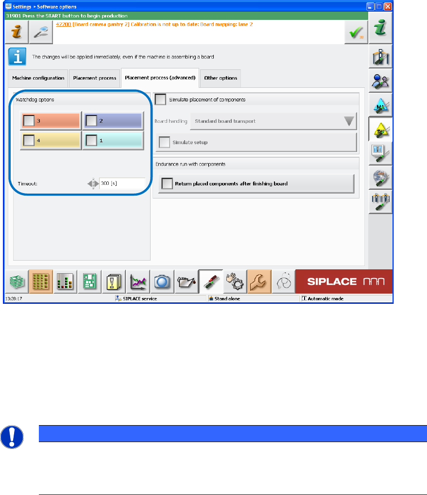
The head axes to be monitored must be selected manually and if required, the monitoring time can
be changed for the current endurance run. Then the monitoring must be enabled via the Watchdog
options check boxes. The set head axes also remain stored after a machine restart.
Figure 9-6: Enabling monitoring
The selected head axes will be monitored after the monitoring has been enabled. If one of these
head axes should not start after the set time, a respective automatic error report will be triggered.
If new / other endurance runs are started or an automatic error report has already been triggered,
the monitoring must be enabled again.
The monitoring must be disabled either via the Watchdog options check boxes or the Stop
button.
NOTICE
If a program is used in dry-run, it must be considered that the placement program
specified in SIPLACE Pro does not contain longer pause times for a head axis as the set
time in the monitoring function. Otherwise, the monitoring function would trigger the error
report.
Station Software 7xx to 714.0 (R20-2) / Feature Description 11/2020 Edition
158
9.11 Conveyor Carrier X for Measurements
Compatible mode: Not supported
For machine accuracy measurements as i.e. ACT or MFU, the glass components in the waffle pack
tray and the glass plate had to be set up on the component table. If required, feeders had to be
removed for this. With the new Conveyor Carrier X, the waffle pack tray and the glass plate can
be set up via the board conveyor instead. Thus, an intervention in the customer setup is avoided
and time saved.
The Conveyor Carrier X occupies one virtual track on the table – like the Arbitrary Carrier X.
The Conveyor Carrier X must be set up manually on any empty track in an opened setup. The
waffle pack tray with the glass components must be set up manually on the carrier as well. Then
the carrier position and the conveyor lane (1 or 2) must be set in SIPLACE Pro.
Fiducials can be defined on the waffle pack tray for a higher pickup accuracy.
As the loaded waffle pack tray is always set to full component filling level, the operator must ensure
that the waffle pack tray is filled.
The board description for the Conveyor Carrier X has to be adapted in SIPLACE Pro. In case of
dual lane conveyor, the conveyor must be operated in synchronous dual conveyor mode.
Additionally, the operator must ensure that the waffle pack tray is available on the second lane.
Restrictions
– No travel range check.
– No pickup simulation.
– The Conveyor Carrier X uses one track on an X-table virtually. If the real table should be
completely occupied, the operator might have to remove a feeder from the table to create place
for the virtual feeder.
– No I-Placement mode.
– The SIPLACE Pro Optimizer does not consider the time it takes to fill up a tray with
components and change it.
9.12 Checking the Placement Heads
Compatible mode: Complete
To reduce unplanned machine stops, the placement heads can be checked with functions of the
SIPLACE Head Care Station. The functions are integrated in the station software and can be
performed for the CPP, C&P20A and C&P20 P placement heads on the Machine service activity
level. The head check mode and the placement head can be selected in the ToolTestBench view.

Station Software 7xx to 714.0 (R20-2) / Feature Description 11/2020 Edition
159
The following checks can be performed:
Checks
CPP
C&P20A
C&P20 P
Component sensor
– Component sensor voltage (contamination)
– Hysteresis (detection of mechanical play)
X
X
X
Hold circuit (air-tightness)
X
X
X
Segment spring mechanism
– Path until addressing the light barrier
– Cushioning path of the segments
X
X
X
Z-axes travel range
– Segment guides (rough running)
X
X
X
Vacuum system
– Air-tightness
– Switching and control behavior of the pressure control valve
X
X
X
Endurance run with low force, Z-axes positioning mode
X
X
X
Endurance run light barriers, Z-axes positioning mode (default
sequence run)
X
X
X
Segment offset (mechanical damages on the segments)
X
X
X
Filter disks (presence and damage)
X
X
Switching disk (installation position)
X
X
DP rotation (DP positioning)
X
Component sensor calibration
X
Controlling the component sensor and light barrier values
dependent on the DP angle
X
Table 9-1: Checks for the placement heads
9.13 New Parameter Set for ECCOBOND D125F with 250µ Needle
Nozzle
To dispense larger glue dots more stably with the ECCOBOND D125F glue type, a new glue
parameter set for a 250µ needle nozzle has been included in the default parameter set. A new
system description (DIPF 1019) has been created to measure the needle nozzle.