SIPLACE Station Software 7xx to 714 介绍.pdf - 第40页
Station Software 7xx to 714.0 (R20-2) / Feature Description 11/2020 Edition 40 5.11 Support of SX4 Placement Machine The station software supp orts the SX4 placement m achine. When the SX4 placement machi ne is booted fo…
Station Software 7xx to 714.0 (R20-2) / Feature Description 11/2020 Edition
39
In SIPLACE Pro it is possible to make settings for the board handling, if no recipe data exists for a
barcode in LineControl:
– The board is transported to the output section of the machine, if an output section exists. The
operator is prompted to remove the board manually. If the machine does not have any output
section from which the board can be removed, the board is transported to the next machine
that has an output section.
– The board is transported to the end of the placing line without being processed.
Barcode controlled production is also possible in synchronous dual lane transport mode.
5.10 Controlled Board Transfer between Placement Machines
With this feature the board individual data is transferred from one placement machine to another
one (Whispering down the Line). The board individual data (e.g. ink spots, barcode, board state,
flag for canceled etc.) are collected in a logical container that is linked to a physical board. When
the board is transferred physically to a placement machine, also the content of the logical container
(or parts of it) gets transferred. The controlled board transfer is supported for lines that are
operated with station software 704. Amongst others, the feature is required for the following
reasons:
1. Transfer of board states (e.g. cancelation, inspection) is required because the machine cannot
be accessed (boards cannot be removed between two placement machines).
As the SX-series placement machines do not have any extension kits, boards are not
accessible at the beginning and the end of the machine and cannot be removed from the line
between two SX placement machines. Therefore, canceled boards are transported down the
line to a machine whose output section is accessible. A station now has to know, if a
transferred board has been canceled in a preceding machine to be able to decide, whether the
board shall be placed or only transported. This information is part of the board individual data.
2. Increased line performance due to reduced downtime (because of the accuracy only ink spot
measurements are transferred).
As the information is transferred, which panels have to be placed, only the first placement
machine in a sub-line has to measure ink spots.
3. Removal of functionality from a SIPLACE placement machine (e.g. barcode scanners).
As the barcode is transferred between the placement machines, only the first placement
machine in a sub-line requires a barcode scanner.
The controlled board transfer is set in SIPLACE Pro and is displayed on the GUI on the "Advanced
Production" activity level under "Settings – Display neighbor machines". Here the preceding
and succeding placement machines and their connection states are visualized. If the connection is
interrupted or the board transfer fails, the operator is guided via dialog boxes in order to correct the
errors.
Station Software 7xx to 714.0 (R20-2) / Feature Description 11/2020 Edition
40
5.11 Support of SX4 Placement Machine
The station software supports the SX4 placement machine.
When the SX4 placement machine is booted for the first time the operator has to select the "SX4
High Speed" entry for "Machine frame" manually in the Auto-configuration, if there are tables in
outer position in processing area 2, as this is not detected automatically via sensors. Tables in
outer position are used when stationary cameras are in use. Otherwise the "SX4 Speed" entry has
to be selected.
5.12 Service Positions for Placement Heads
New C&P20A and CPP placement heads get furnished with a head marker that shows the
respective service position. The head marker is situated directly on the placement head and is
indicated by a white triangle in Manual Operations. The service position can be adjusted.
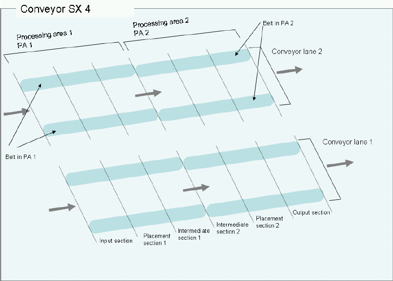
5.13 Support of SX4 Conveyor Type
The station software supports the new SX4 conveyor type with 2 conveyor lanes and 6 sections
(sections = formerly belts).
Figure 5-2: SX4 conveyor type

Station Software 7xx to 714.0 (R20-2) / Feature Description 11/2020 Edition
41
5.13.1 Flexible Section Model in the Conveyor Interface
In order to support a variable number of sections, a flexible section model has been added to the
conveyor interface. The section model supports up to 6 sections and the corresponding board
messages and data, like e.g. stop positions.
SX1/2: 3 sections (Input section, Placement section, Output section)
X4/X4i: 5 sections (Input section, Placement section 1, Intermediate section 1, Placement
section 2, Output section)
SX4: 6 sections (Input section, Placement section 1, Intermediate section 1, Intermediate
section 2, Placement section 2, Output section)
5.13.2 Stop Positions for Fixed Conveyor Rail – Conveyor Configurations
All permitted conveyor configurations for the X-series and SX-series placement machines are listed
in the following table:
Frame
Fixed conveyor rail in mm from the center of the machine
191
230
231
234,2
254
256
268
270
281
341
customized
X,
single
-
X
-
-
X
-
X
-
-
-
X
X, dual
-
-
-
X
X
-
X
-
-
-
X
X,
Quad
Lane
-
-
-
-
-
-
X
-
-
-
X
SX1/2,
single
X
-
X
-
-
X
-
-
X
-
-
SX1/2,
dual
-
-
-
X
X
-
X
-
X
-
X
SX4,
dual
-
-
-
-
-
-
X
-
X
X
X
SX4,
Quad
Lane
-
-
-
-
-
-
-
X
X
X
X
Table 5-1: Stop positions for fixed conveyor rail - conveyor configurations
5.14 LDU_X Module – Multiple Squeegee Cycles, Warnings
Dependent on the consistency of the flux media a single squeegee cycle might not be sufficent to
initially apply the flux media evenly. Therefore, it is possible to activate multiple squeegee cycles at
once in the following cases:
– the safety circuit of the machine gets closed (e.g. after the cover was opened)
– the operator activates a squeegee cycle via the GUI
In all other cases a single squeegee cycle will be performed.
The number of the squeegee cycles can be changed on the GUI as of the "Machine Service"
activity level. Default value is 1. After removing the LDU or rebooting the machine, the default value
is valid again.
Additionally, warnings are displayed on the GUI, for example referring to a low filling level.