SIPLACE Station Software 7xx to 714 介绍.pdf - 第58页
Station Software 7xx to 714.0 (R20-2) / Feature Description 11/2020 Edition 58 6.22 Maintenance Due Status for C&P20A Placement He ad and SX Main Axes As of this station software version, the maintenance due statu s …
Station Software 7xx to 714.0 (R20-2) / Feature Description 11/2020 Edition
57
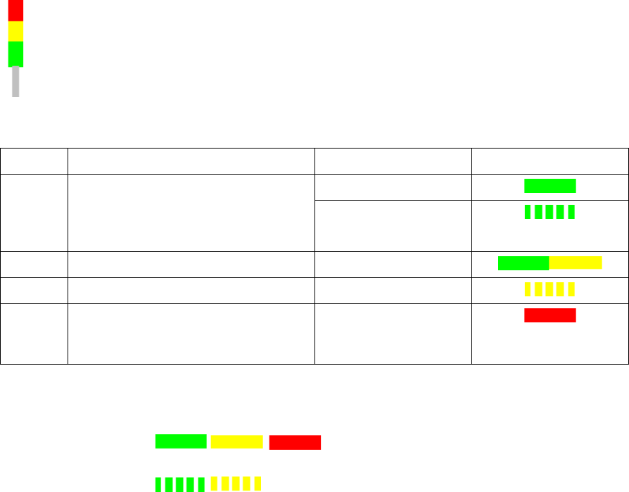
6.19 Setting Lamp Indicator (Two-Colored or Three-Colored)
The towers of the X-, SX- and DX-series placement machines are equipped with two lamp
indicators (one on each side of the machine). Until now these lamp indicators were two-colored
(green / white) on the X- and SX-series placement machines. With the aid of the different states of
the single lamp indicators (including the flashing frequency) the operator can recognize the
machine status (i.e. production, waiting state, error type etc.). Additionally, a three-colored lamp
indicator (green / yellow / red) is supported as of this station software version:
The three-colored lamp indicator is explicated in the following table.
Level
Action
Machine state
Lamp indicator
1
none
Production
– Manual operation
– Idle production
2
Attention required
Production
3
Immediate reaction
Break / Stopped
4
Immediate reaction
(technical assistance might be
required)
Down
Table 6-1: Three-colored lamp indicator
Key
Constantly
illuminated:
Flashing:
The relative lamp indicator (two-colored or three-colored) must be set in the Auto-configuration, see
the installation manual to the station software, item no. [00196771-xx].
6.20 Two-Row Nozzle Changer on SX1/SX2 for C&P20A and CPP
The two-row nozzle changer is supported for the C&P20A and CPP placement heads on the
SX1/SX2-series placement machines.
6.21 Extended Range for Customized Nozzles for CPP and Twin Head
The range for customized nozzles has been extended as follows:
– Twin Head: 5500-5999 (5xx) nozzles
– CPP head: 2500-2799 (20xx) and 2900-2999 (28xx)
Station Software 7xx to 714.0 (R20-2) / Feature Description 11/2020 Edition
58
6.22 Maintenance Due Status for C&P20A Placement Head and SX
Main Axes
As of this station software version, the maintenance due status can be calculated for the C&P20A
placement head and the SX main axes. The maintenance due status of the single components is
displayed in the Maintenance due status view on the GUI and informs about the maintenance due
date for the component.
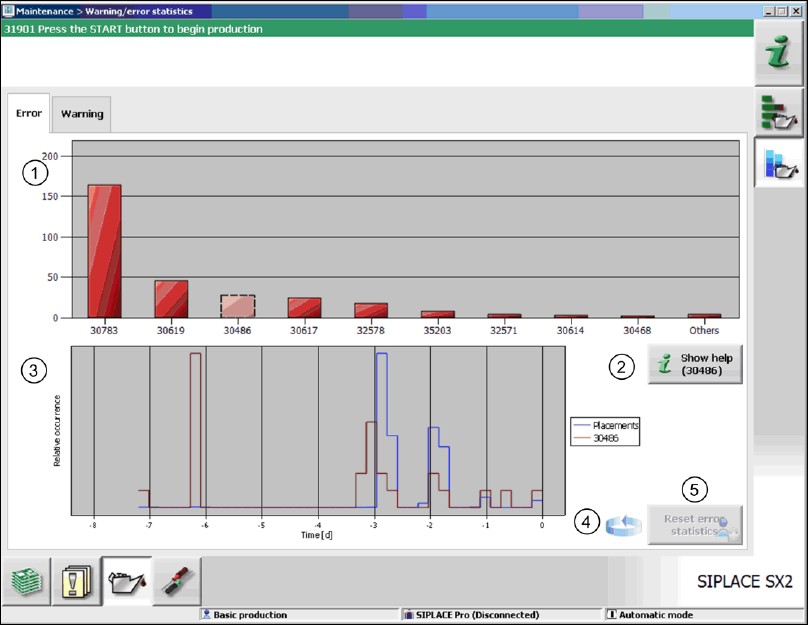
6.23 Optimized Display and Format of Warnings / Alarms
The display and format of warnings / alarms have been optimized. Only the absolutely necessary
warnings are displayed in the status area on the GUI. Warnings / alarms are collected in a new
view. With this information problems that occurred on the machine in the last few days can be
specifically solved before a planned maintenance.
The collected warnings and alarms are displayed on the GUI in the Maintenance view.
Figure 6-7: Statistics for warnings / alarms
In the upper part of the view, the ten most frequently occurred alarms / warnings are displayed (1).
After an error number has been selected in the diagram, the corresponding online help can be
accessed via the Show help button (2).
In the lower part of the view, the characteristics for the occurrence of the selected error message
are roughly displayed (red graph) in relation to the placement performance (blue graph) for the
observation period (3).
By clicking on the rotating arrow (4) a table appears, in which the assignment of the selected
messages to the messaging sub-systems is displayed. Thus the operator can easily find out where
they arose.
Old entries are automatically removed from the statistics. If necessary, the operator can reset the
statistics explicitly via the Reset error statistics button (5) as of the Machine service activity
level.

Station Software 7xx to 714.0 (R20-2) / Feature Description 11/2020 Edition
59
6.24 Machine Behavior at Cover Foil Torn
In previous station software versions the placement heads get stopped when a cover foil torn
occurs and this always causes a machine stop. As of this station software version the machine
behavior has been specifically configured for the placement heads as follows:
C&P20A Machine stop
Twin Head No machine stop
CPP No machine stop
C&P12 No machine stop
Features for the DX-Series (V705.03)
The station software supports the new DX1/DX2 and DX4 placement machines that are based on
the corresponding SX1/SX2 and SX4 placement machines. The features of the 705.03 station
software version for the DX-series are listed in the sections 6.25 to 6.29.
6.25 General
The DX1/DX2 placement machines differ from the SX1/SX2 placement machines as follows:
– B C&P12 placement head instead of CPP placement head.
– The 27x27 reject bin and the left reject channel fail.
– If two C&P12 placement heads exist, there are two machine zero points.
– If the placement head shall be omitted via the configuration, it must be selected in the Auto-
configuration, whether the omitted placement head is a Twin Head/C&P20A or a C&P12.
– Support of DX-tables and changeover tables.
– The DX1/DX2 placement machines cannot be upgraded with regard to the number of gantries.
The number of gantries is already selected during the software installation and is not part of the
Auto-configuration.
During the first booting after installation of the station software, the following options must be
selected manually in the Auto-configuration fort he DX-series placement machines:
– For the C&P12 placement head: height position (altitude)
– Lamp indicator (two-colored or three-colored)
– Table positions:
60 slots (inner position)
60 slots (outer position)
30 slots (outer position) with 30 slots + free location for tray or WPC
NOTICE
– No upgrade from DX to SX!
– No head or gantry modularity, i.e. no remodeling is performed from one head or
gantry type to another in the field.