SIPLACE Station Software 7xx to 714 介绍.pdf - 第268页
Station Software 7xx to 714.0 (R20-2) / Feature Description 11/2020 Edition 268 Features (V713.1 (R20 -1): Compatible Mode 712.3 ) 14.16 Adjusting Sigma Leve l for Accuracy Check Tool (ACT) Re sults Compatible mode: Comp…

Station Software 7xx to 714.0 (R20-2) / Feature Description 11/2020 Edition
267
14.12 Changes With HERMES-IPC-9852 Version 1.2
Compatible mode: Complete
The station software fully complies with HERMES-IPC-9852 V1.2. In order to visualize the Vertical
Channel messages, the Vertical channel tab has been added to the IPC-HERMES-9852 events
under Messages. In this tab, the traffic on the HVC (Hermes Vertical Channel) with all running
sessions and the corresponding client systems can be viewed.
14.13 New Fiducial Type “Edge” Supported
Compatible mode: Complete
The new fiducial type “Edge” is supported. With this new fiducial type, it is possible to define the
run of an edge, which is useful for LED alignments. The fiducial is visualized as a hatched line, as
shown in the following icon:
14.14 Inspecting Components After Placement at Too High Speed
Compatible mode: Complete
If the PCB description is incorrect or if there are bends in the PCB, the nominal position of the PCB
top edge might deviate distinctly. The component might therefore be placed at too high speed, and
consequently, get damaged.
If such an event occurs, the respective placement position is set to “inspect” and the error
40084 Component on board is possibly damaged is displayed. The error provides images from
the PCB camera of the component at the placement position and at the nozzle which can be used
to inspect the component for damages. The error can be solved with one of the following options:
– Component is not damaged: continue producing
– Component is damaged: skip panel
– Component is damaged: cancel board
14.15 “SIPLACE Service” Button Permanently Visible in Station GUI
The SIPLACE service button in the station GUI is now permanently available to enter the service
password. The key sequence that was previously used to open the SIPLACE service is no longer
supported.
Station Software 7xx to 714.0 (R20-2) / Feature Description 11/2020 Edition
268
Features (V713.1 (R20-1): Compatible Mode 712.3)
14.16 Adjusting Sigma Level for Accuracy Check Tool (ACT) Results
Compatible mode: Complete
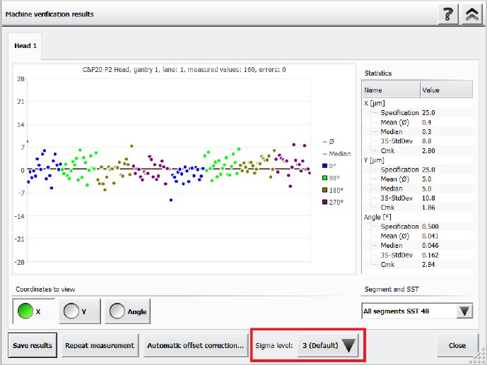
The Accuracy Check Tool (ACT) is used to determine the placement accuracy of a specific
placement head and, if necessary, correct it. If an ACT check is performed, components are
measured after placement and the results are displayed in the Machine verification results
dialog.
It is now possible to adjust the sigma level in this Machine verification results dialog via the new
Sigma level drop-down list. The selectable sigma levels in the list range from the configured
default value (usually 3 or 4) up to maximum level 6.
Figure 14-2: Adjusting the sigma level in the ACT Results dialog
If a new measurement is done, the results in the Machine verification results dialog are displayed
according to the default sigma level value that has been configured for the station. When you
change the sigma level, the results within the Machine verification results dialog are refreshed
accordingly. Additionally, the +/- specification values for X, Y and Angle are listed in the statistical
results on the right side of the dialog.
When generating a PDF report, the statistical data in the PDF matches the sigma level that has
been selected when the PDF report has been generated. You can change the sigma level after
generating a PDF report, but please note that if you want to generate a new PDF report with the
new sigma level, you need to repeat the measurement.
The general ACT behavior is not changed by this enhancement, i.e. the values for the offset
correction are independent from the selected sigma level. To repeat the manual correction, a new
ACT placement is needed.
For further information on ACT, please refer to the ACT User Manual, item no. [00196351-xx].
Station Software 7xx to 714.0 (R20-2) / Feature Description 11/2020 Edition
269
14.17 Support of SIPLACE TX2 V2 HD / SIPLACE TX2i V2 HD
The hardware upgrade kit High Density option package TX, item no. [588510-xx] for the
SIPLACE TX2 V2 / TX2i V2 is supported.
With a conveyor update and corresponding X-Fiducials contained in the hardware upgrade kit, a
SIPLACE TX2 V2 / TX2i V2 can be remodeled to a SIPLACE TX2 V2 HD / TX2i V2 HD. These
upgraded machine types can perform high density placement.
Original Machine
Type
Placement Heads
Upgraded
Machine Type
SIPLACE TX2 V2
2x CPP placement heads
(low position) with SST30
TX2 V2 HD
SIPLACE TX2i V2
2x CP20 P2 placement heads with SST48
TX2i V2 HD
2x CP20 P2 placement heads with SST49
1x CP20 P2 placement head with SST48
+ 1x CP20 P2 placement head with
SST49 (mixed camera configuration)
Table 14-1: Overview of high density placement upgrade option per machine type
NOTICE
When upgrading a machine type, the station software needs to be reinstalled on that
machine.
Restrictions
– The new machine types do not support Smart Pin Support.
14.18 Configuring Tolerance Values for Resetting the Conveyor Width
Compatible mode: Complete
If the Automatic Width Adjustment option has been activated on the Line Control GUI and the
conveyor width of the lane differs from the width specifications in the recipe (e.g. because it has
been manually changed for maintenance), the conveyor width is automatically reset to the width
specifications from the recipe at the start of production.
But even if the Automatic Width Adjustment option is deactivated, the conveyor width is reset to
the width specified in the recipe at the start of production if the conveyor width has been manually
changed further than a configured tolerance allows.