SIPLACE Station Software 7xx to 714 介绍.pdf - 第177页
Station Software 7xx to 714.0 (R20-2) / Feature Description 11/2020 Edition 177 The operator now has to set the rail positions manually via the Find fiducial posi tion button. Figure 10 -1: Finding fiduci al position NOT…

Station Software 7xx to 714.0 (R20-2) / Feature Description 11/2020 Edition
176
10.1.2 SIPLACE TX Conveyor System
A new conveyor system has been introduced for the SIPLACE TX-series.
SIPLACE TX consists of one input section (410 mm), one placement section (380 mm) and one
output section (210 mm). The conveyor supports asynchronous and synchronous dual lane mode
and the I-Placement option as well. Optionally, the new Flexible Dual Lane – Machine Connection
Bound license can be purchased to support the dual lane in single lane mode. This license is
bound to a single station.
The fixed rails are pre-set and mechanically fixed at the outer positions (conveyor lane 1 – to the
right, conveyor lane 2 – to the left). Rail positions: 231.0 mm, 268.0 mm and 281.0 mm. If
necessary, the fixed rails can be mounted to the positions right/right or left/left. User-defined rail
positions are not supported.
The dual lane in single lane mode is only possible with the fixed rails in the outer position. A new
mapping is required the first time this option is activated. When changing to this mode, it is
necessary to remove the mechanical limit stops, which are located between the two lanes.
Therefore, a user interaction will be necessary before starting the rail configuration adjustment
process. The necessary instruction(s) will be displayed via a detailed error message.
Height reference run and leakage test are automatically performed on the fixed rail.
In dual lane mode the width adjustment of the two lanes will start simultaneously. Maximum board
width = 260 mm and maximum board length = 375 mm. With dual lane in single lane mode, the
maximum board width is 460 mm. The Long Board, Wide Board, Thick Board and Heavy Board
options are not supported.
For boards up to 175 mm, the TX conveyor can handle two boards in the placement section of the
machine (Convoy mode). Thus, the board transport time is reduced. An additional stopper collects
the boards before they are transported into the placement section. The Convoy mode is enabled
by default but can be disabled under Service – Conveyor configuration – Lane x – Parameters.
Optionally, input and output conveyor extensions (e.g. for barcode scanner, JTF-ML feeder) and
vacuum tooling may be ordered.
10.1.2.1 Conveyor Reference Run with Board Camera
Due to the mechanics of the TX conveyor system, a special reference run with board camera is
used to determine the rail positions.
During the reference run the software checks if the rail positions have been changed and issues an
estimated position for each rail. After that, the board camera checks if fiducials using these
positions are present on each rail. If yes, these positions are transmitted to the conveyor system for
update.
However, as the rail positions can be changed by the operator while the machine is switched off
and this cannot be recognized neither by the software nor the hardware, the estimated positions
might be invalid. In this case the board camera does not find any fiducials on the rails and a
detailed error message is displayed.
NOTICE
Some workflows, e.g. calibration, may not be interrupted by detailed error messages. In
such cases the workflow will be completed, and a general error message displayed.
During the next regular reference run the error can be corrected via the detailed error.
Station Software 7xx to 714.0 (R20-2) / Feature Description 11/2020 Edition
177
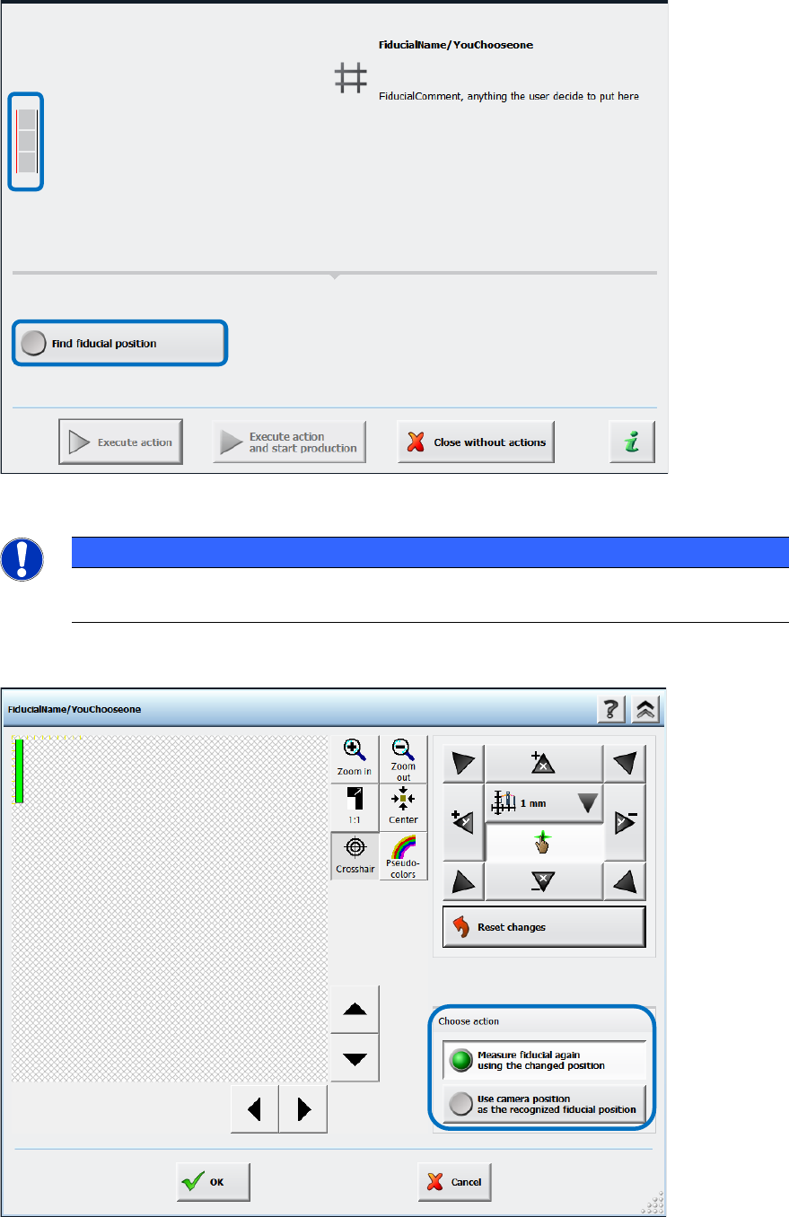
The operator now has to set the rail positions manually via the Find fiducial position button.
Figure 10-1: Finding fiducial position
NOTICE
► Please pay attention to the small icon to the left of the detailed error text!
A thin red line indicates which fiducial could not be found on which conveyor rail.
In the next dialog the camera must be moved until the fiducial is clearly positioned in the field of
view.
Figure 10-2: Setting fiducial position manually
Station Software 7xx to 714.0 (R20-2) / Feature Description 11/2020 Edition
178
The new position can either be used as starting point for a new measurement (Measure fiducial
again using the changed position option) or as new fiducial position (Use camera position as
the recognized fiducial position option).
If the machine has not been (correctly) calibrated, the positions issued by the board camera might
be incorrect. Therefore, whenever a calibration is performed that affects the result of the rail
position check, the reference state of the conveyor system is invalidated, and a new rail position
check is started before the conveyor system can be used again.
10.1.2.2 Mapping in Dual Lane Mode with New Mapping Plate
Mapping can be performed in dual lane mode on the TX-series placement machines and the
mapping plates can reside simultaneously on both lanes. For mapping in dual lane mode, the
maximum conveyor lane width is used (= maximum board width 260 mm). However, mapping in
dual lane mode is performed sequentially for accuracy reasons.
For mapping in dual lane mode, a new mapping plate has been designed. The plate is 440 mm x
260 mm and the distance between the fiducials 19 mm.
Optionally, mapping can be performed by using the maximal width of the dual lane conveyor in
single lane mode (= maximum board width 460 mm). In this mode the existing mapping plate of the
SX-series will be used (560 mm x 460 mm).
The mapping mode must be selected under Machine Service – Automatic calibration.
10.1.3 Feeder Types, Tables and Other Devices
SIPLACE TX-series supports the following feeder types, tables and devices:
– Change Over Table 40X (40 x 8 mm X-feeders)
– New SIPLACE JTF-ML Table 40X (40 tracks, on location 1 only)
– Tape feeders (4 mm – 56 mm)
– SIPLACE Glue Feeder
– Dip modules (2 per location; 1 dip module + 1 tower per table)
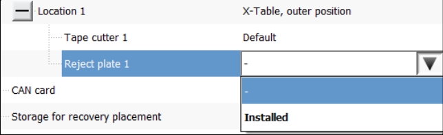
– Reject plate
This is a fixed mounted plate on which the station can put rejected components after the
SIPLACE Vision system detected errors instead of into the reject bin. The reject plate can be
specified as option in SIPLACE Pro and is enabled in the Auto configuration of the station
software:
Figure 10-3: Selecting reject plate
Currently, a reject plate can only be installed on location 1. The entry must be disabled
explicitly if no reject plate is installed.
Detailed errors are displayed when the reject plate is full or when the plate must be emptied
during a setup change. Within the detailed errors the operator can confirm that the reject plate
is empty.