SIPLACE Station Software 7xx to 714 介绍.pdf - 第180页
Station Software 7xx to 714.0 (R20-2) / Feature Description 11/2020 Edition 180 10.1.5 Calibration of Twin Head with Stationary Flip Chip Camera and Calibration Nozzle For lack of space, stationary I C and Flip Chip came…
Station Software 7xx to 714.0 (R20-2) / Feature Description 11/2020 Edition
179
– New tray feeder SIPLACE JTF-ML
The SIPLACE JTF-ML tray feeder is inserted from the conveyor side and uses the same XFCU
as all other feeders on location 1. The SIPLACE JTF-ML is connected via a dummy feeder that
is inserted on track 29 and occupies 12 tracks.
The SIPLACE JTF-ML can be combined with the CPP (in high position) and Twin Head
placement heads.
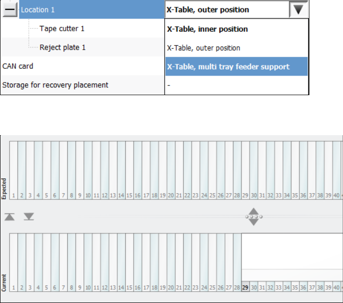
If the SIPLACE JTF-ML is used, the operator must set the X-Table, multi tray feeder support
option for the JTF-ML Table 40X on location 1 in the auto configuration. If the station software
is running simultaneously, the software must be restarted after the change.
Figure 10-4: Setting table for SIPLACE JTF-ML
The feeder view is displayed in the Table dialog as usual.
Figure 10-5: Feeder view SIPLACE JTF-ML
10.1.4 Rejection of Large Components
Components with a maximum size of 55 mm x 45 mm can be rejected into a reject bin with a size
of 110 mm x 70 mm.
The preferred way of rejecting components is to drop the component with its center onto the center
of the reject bin. Currently, when a component is rejected, the rotation angle of it is 0°.
However, the centers of some reject bins are not reachable with every segment of every placement
head, especially not by the Twin Head. Additionally, when decentralized pickup of components is
used, it is not possible to align both centers when the component angle is 0°.
Therefore, the component is rotated to the optimal angle, to position the component center as close
as possible to the center of the reject bin.
Station Software 7xx to 714.0 (R20-2) / Feature Description 11/2020 Edition
180
10.1.5 Calibration of Twin Head with Stationary Flip Chip Camera and Calibration
Nozzle
For lack of space, stationary IC and Flip Chip cameras cannot be mounted simultaneously in the
SIPLACE TX-series placement machines. Therefore, the Flip Chip camera is used together with a
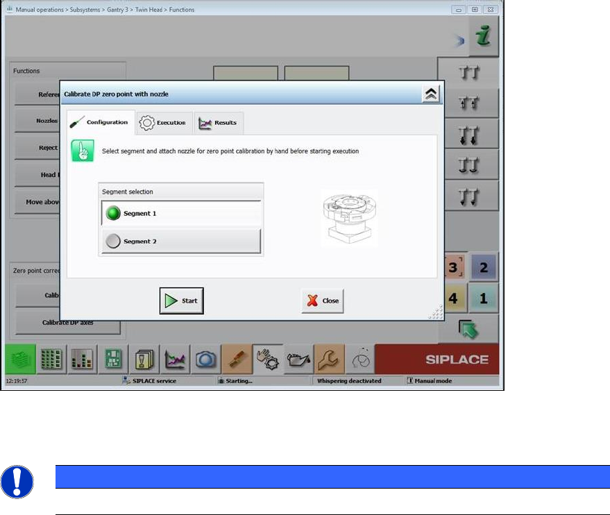
special calibration nozzle (no. 502) to calibrate the Twin Head.
The software checks if the calibration must be performed with the calibration nozzle, i.e. if no IC
camera is mounted. The operator is prompted on the GUI to attach the calibration nozzle on a
segment of the Twin Head and confirm it in the Manual operations.
Figure 10-6: Attaching calibration nozzle
The procedure must be performed separately for each segment.
HINWEIS
The calibration nozzle must not be used as a standard nozzle!
10.1.6 Calibration Steps to Support Machine Dynamics
To achieve higher accuracy of the gantry axes, the following two calibration steps must be set
under Machine Service – Automatic calibration:
– X-axis parametrization
– System identification
The results are automatically stored without confirmation.
Station Software 7xx to 714.0 (R20-2) / Feature Description 11/2020 Edition
181
10.1.7 Fast Head Exchange
The Fast Head Exchange option is supported for the C&P20 P and CPP placement heads on the
TX-series machines in the same way as for the X-series machines and with the same restrictions.
Additionally, the "X-axis parametrization" step is performed during calibration. Please also refer to
section 10.9.1.
10.1.8 Fault-Tolerant Operation
To prevent a complete line down time, the placement head of each gantry can be set to "No head
installed".
This state can be enabled and disabled in the Auto Configuration under Service – Machine
configuration.
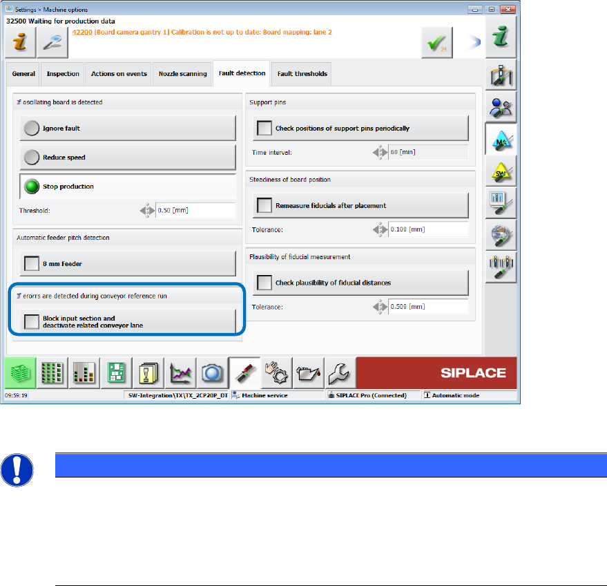
If errors occur during the conveyor reference run, the related conveyor lane can also be disabled
under Settings – Machine options – Fault detection.
Figure 10-7: Disabling conveyor lane
NOTICE
The Auto configuration cannot distinguish between a TX1 machine with no placement
head on gantry 2 and a TX2 machine with disabled placement head on gantry 2.
Therefore, if the placement head is disabled on gantry 2 of the TX2 machine, the nozzle
changer configuration for the TX1 machine will be configured and all nozzle and
calibration data on location 2 deleted. After reactivating the placement head on gantry 2
of the TX2 machine, the nozzle changer on location 2 must be calibrated
10.1.9 Checking the Fans
– The state of all fans is retrieved and displayed under Subsystems on the station software GUI.
– A fan check can be performed during maintenance, see section 10.9.