SIPLACE Station Software 7xx to 714 介绍.pdf - 第279页
Station Software 7xx to 714.0 (R20-2) / Feature Description 11/2020 Edition 279 15.6 Tray Teaching Dialog – Enhancements Compatible mode: Complete Previously, when editing a tray descri ption, there were two dialogs avai…
Station Software 7xx to 714.0 (R20-2) / Feature Description 11/2020 Edition
278
15.3 New Hardware Supported on SIPLACE TX2 V2
Compatible mode: Not supported
The following hardware is supported on the SIPLACE TX2 V2:
– C&P20 P2 placement head
– C&P20 P2 placement head together with CPP placement head in low position in mixed mode
– SIPLACE JTF-ML2 (JEDEC Tray Feeder), item no. [00588116]
15.4 Smart Pin Support – Changed Behavior for Product Changeover
Sequence
Compatible mode: Complete
The behavior during product changeover has changed. In the old product changeover sequence,
whenever the conveyor rail configuration or the conveyor width changed, all installed support pins
were first removed before the conveyor rails were adjusted. Once the conveyor rail adjustment was
finished, the support pins were installed again according to the new product specifications.
With the new behavior, the support pins are only completely removed when a new conveyor rail
configuration is implemented.
If the conveyor width is increased, the support pins remain inside the machine while the new
increased conveyor width is set. Once the new conveyor width is set, the support pins are adjusted
according to the new product.
If the conveyor width is decreased, the support pins are first adjusted according to the new product
before the new decreased conveyor width is set.
If a new conveyor rail configuration is implemented, the support pins are removed completely
before the rails are adjusted. Afterwards, the support pins are installed in the machine again.
15.5 Combination of CPP M and CP20 M3 Placement Heads Supported
in TX micron V2
Compatible mode: Not supported
It is now possible to combine a CPP M placement head and a CP20 M3 placement head in a
TX micron V2 placement machine. Since the CPP M placement head is able to place taller
components than a CP20 M3 placement head, the CPP M placement head can fly over taller
components, whereas the CP20 M3 placement head has to move around these taller components
to avoid head crashes.
When a CPP M placement head and a CP20 M3 placement head are combined in a TX micron V2
placement machine, cyclic recalibration is only started when no board with tall components is
located in the processing area or in the output section. This way, the CP20 M3 placement head can
reach the x- or y-fiducial bar for recalibration without risk of head crashes. If a board is located in
either the processing area or the output section, a corresponding message is displayed at the
station GUI. Once the recalibration is finished, the production of new boards proceeds.
Restrictions:
– To combine a CPP M placement head and a CP20 M3 placement head in a TX micron V2
placement machine, the TX2i Mixed Heads conversion kit, item no. [03157293-xx] is required.
Station Software 7xx to 714.0 (R20-2) / Feature Description 11/2020 Edition
279
15.6 Tray Teaching Dialog – Enhancements
Compatible mode: Complete
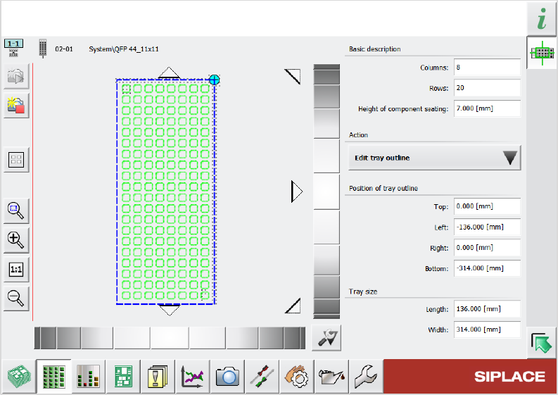
Previously, when editing a tray description, there were two dialogs available to do so: A “simplified”
dialog and an “advanced” dialog. These two dialogs have now been merged into one single dialog.
This new dialog has the same layout as the previous simplified dialog with additional functions from
the advanced dialog. The picklist in the Selected pocket group from the simplified dialog has been
renamed Action and now contains an Edit tray outline option. With this option, you can determine
the position of the tray using the schematic graphic on the left and edit the numerical values of the
position and the size of the tray.
Figure 15-2: New dialog for editing tray description
15.7 Component Camera (Type 48) 8x8 GigE and PCB Camera
(Type 54) Supported
Compatible mode: Hidden
The following new camera types are supported:
– Component Camera (Type 48) 8x8 GigE for E by SIPLACE placement machines
– PCB Camera (Type 54)

Station Software 7xx to 714.0 (R20-2) / Feature Description 11/2020 Edition
280
15.8 Automatic Recognition of XX Nozzle Magazine Change on
Prepare for Production
Compatible mode: Complete
After restarting the station software, or after exchanging a nozzle magazine, the nozzle magazine
types are checked via the fiducials at the start of production and exchanged automatically, if
necessary. Afterwards, the garages of the magazine, or the nozzle contained in it, are scanned. If a
magazine was exchanged, the already measured height of the previous magazine is taken over, so
there is no need to calibrate again. If no height measurement value is available, then the magazine
must be calibrated once.
The function can be disabled with the Skip nozzle id scanning check box in the Check and set
software options - Machine configuration dialog.
Restrictions:
– The nozzle changer must be connected to XFCU (Feeder Control Unit for X-tables).
– This function is not supported for twin nozzle magazines.
– The magazines can only be automatically exchanged during production preparation before
nozzle type scanning and not during manual functions or the calibration of nozzle magazines.
– Each spot in the magazine must be fully calibrated at least once in order to use the automatic
nozzle magazine exchange. Please note that for the measurement of the z-height, a calibration
nozzle is necessary.
15.9 Verifying Clinching Tool by Barcode Fiducial
Compatible mode: Complete
NOTICE
Please contact ASM service if you want to activate this feature.
A Clinching tool consists of a plate with several beveled pins on top that is installed in a placement
machine. After placement of THT components (e.g. capacitors), this plate is pressed to the
underside of the PCB to clinch the leads of the THT components.
Whenever you use a clinching tool in a station, you need to configure it in the recipe in SIPLACE
Pro and in the station software. To verify that the correct clinching tool has been installed in the
station, the configuration on the station is compared with the specifications in the recipe. To
automatically identify the clinching tool installed in the station, a barcode fiducial can be used that
is placed on the clinching tool surface. The barcode contains information on the clinching tool, e.g.
its name and exact clinching tool type.
During recipe download, when the conveyor is empty, the clinching tool and the lifting table are
lifted to upper position, where the barcode on the tooling surface can be scanned by the PCB
camera. The information contained on the barcode is then compared to the specifications in the
recipe. If the barcode cannot be read, if the clinching tool type is unknown, or if the information in
the barcode does not match the data stored in the station software configuration, a corresponding
detailed error message is displayed: