SIPLACE Station Software 7xx to 714 介绍.pdf - 第178页
Station Software 7xx to 714.0 (R20-2) / Feature Description 11/2020 Edition 178 The new position can eithe r be used as starting point for a new m easurement ( Measure fiducial again using the changed position option) or…
Station Software 7xx to 714.0 (R20-2) / Feature Description 11/2020 Edition
177
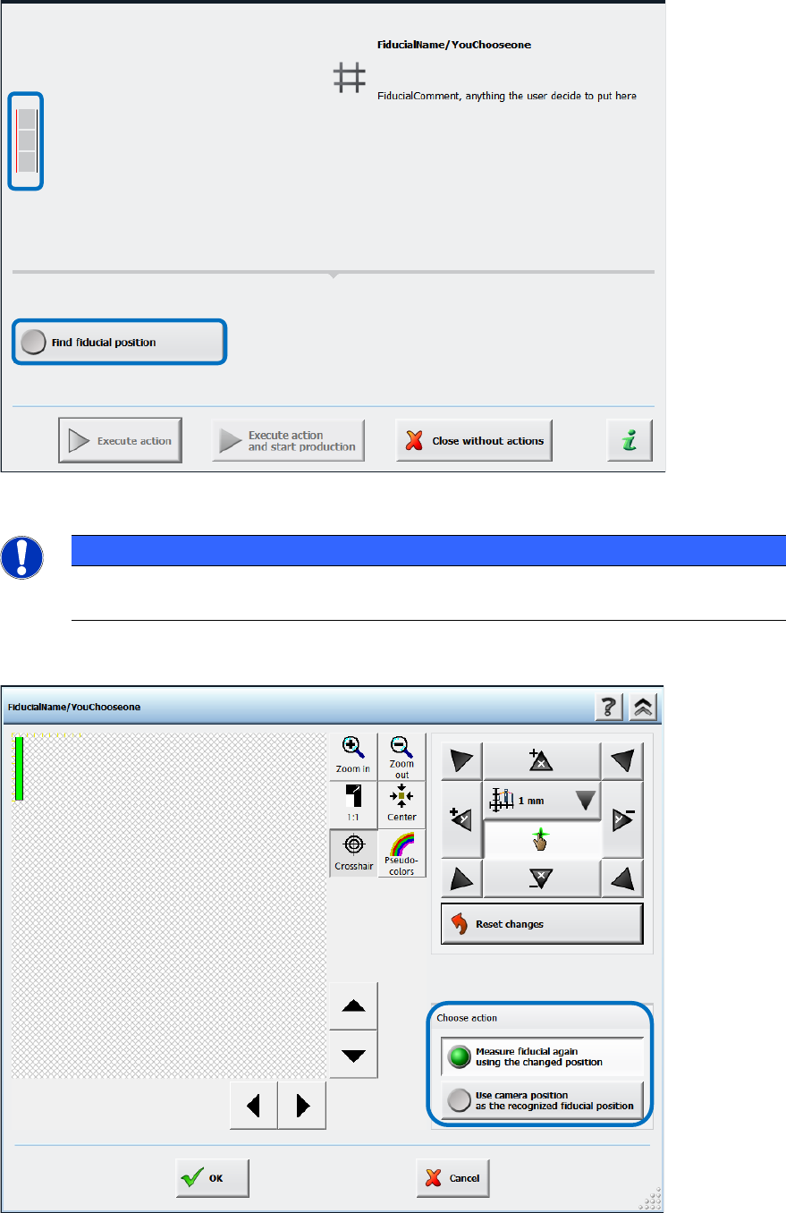
The operator now has to set the rail positions manually via the Find fiducial position button.
Figure 10-1: Finding fiducial position
NOTICE
► Please pay attention to the small icon to the left of the detailed error text!
A thin red line indicates which fiducial could not be found on which conveyor rail.
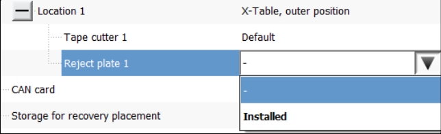
In the next dialog the camera must be moved until the fiducial is clearly positioned in the field of
view.
Figure 10-2: Setting fiducial position manually
Station Software 7xx to 714.0 (R20-2) / Feature Description 11/2020 Edition
178
The new position can either be used as starting point for a new measurement (Measure fiducial
again using the changed position option) or as new fiducial position (Use camera position as
the recognized fiducial position option).
If the machine has not been (correctly) calibrated, the positions issued by the board camera might
be incorrect. Therefore, whenever a calibration is performed that affects the result of the rail
position check, the reference state of the conveyor system is invalidated, and a new rail position
check is started before the conveyor system can be used again.
10.1.2.2 Mapping in Dual Lane Mode with New Mapping Plate
Mapping can be performed in dual lane mode on the TX-series placement machines and the
mapping plates can reside simultaneously on both lanes. For mapping in dual lane mode, the
maximum conveyor lane width is used (= maximum board width 260 mm). However, mapping in
dual lane mode is performed sequentially for accuracy reasons.
For mapping in dual lane mode, a new mapping plate has been designed. The plate is 440 mm x
260 mm and the distance between the fiducials 19 mm.
Optionally, mapping can be performed by using the maximal width of the dual lane conveyor in
single lane mode (= maximum board width 460 mm). In this mode the existing mapping plate of the
SX-series will be used (560 mm x 460 mm).
The mapping mode must be selected under Machine Service – Automatic calibration.
10.1.3 Feeder Types, Tables and Other Devices
SIPLACE TX-series supports the following feeder types, tables and devices:
– Change Over Table 40X (40 x 8 mm X-feeders)
– New SIPLACE JTF-ML Table 40X (40 tracks, on location 1 only)
– Tape feeders (4 mm – 56 mm)
– SIPLACE Glue Feeder
– Dip modules (2 per location; 1 dip module + 1 tower per table)
– Reject plate
This is a fixed mounted plate on which the station can put rejected components after the
SIPLACE Vision system detected errors instead of into the reject bin. The reject plate can be
specified as option in SIPLACE Pro and is enabled in the Auto configuration of the station
software:
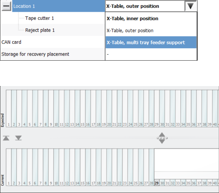
Figure 10-3: Selecting reject plate
Currently, a reject plate can only be installed on location 1. The entry must be disabled
explicitly if no reject plate is installed.
Detailed errors are displayed when the reject plate is full or when the plate must be emptied
during a setup change. Within the detailed errors the operator can confirm that the reject plate
is empty.
Station Software 7xx to 714.0 (R20-2) / Feature Description 11/2020 Edition
179
– New tray feeder SIPLACE JTF-ML
The SIPLACE JTF-ML tray feeder is inserted from the conveyor side and uses the same XFCU
as all other feeders on location 1. The SIPLACE JTF-ML is connected via a dummy feeder that
is inserted on track 29 and occupies 12 tracks.
The SIPLACE JTF-ML can be combined with the CPP (in high position) and Twin Head
placement heads.
If the SIPLACE JTF-ML is used, the operator must set the X-Table, multi tray feeder support
option for the JTF-ML Table 40X on location 1 in the auto configuration. If the station software
is running simultaneously, the software must be restarted after the change.
Figure 10-4: Setting table for SIPLACE JTF-ML
The feeder view is displayed in the Table dialog as usual.
Figure 10-5: Feeder view SIPLACE JTF-ML
10.1.4 Rejection of Large Components
Components with a maximum size of 55 mm x 45 mm can be rejected into a reject bin with a size
of 110 mm x 70 mm.
The preferred way of rejecting components is to drop the component with its center onto the center
of the reject bin. Currently, when a component is rejected, the rotation angle of it is 0°.
However, the centers of some reject bins are not reachable with every segment of every placement
head, especially not by the Twin Head. Additionally, when decentralized pickup of components is
used, it is not possible to align both centers when the component angle is 0°.
Therefore, the component is rotated to the optimal angle, to position the component center as close
as possible to the center of the reject bin.