SIPLACE Station Software 7xx to 714 介绍.pdf - 第200页
Station Software 7xx to 714.0 (R20-2) / Feature Description 11/2020 Edition 200 10.13.6 Camera Connections – Checking Gig E Interface A new GUI dialog will provi de information about the current health states of permanen…
Station Software 7xx to 714.0 (R20-2) / Feature Description 11/2020 Edition
199
10.13.3 Machine Verification – Keeping Programs Stored on the Station
Downloaded programs for machine verification and placement force can be stored permanently on
the station. Thus, only one download is necessary, and the programs can be recalled for further
measurements. If the configuration changes (= new ACT program name), the programs can be
removed manually from the station and the current ones downloaded from SIPLACE Pro. If the
same program is downloaded again, it will be overwritten at the station.
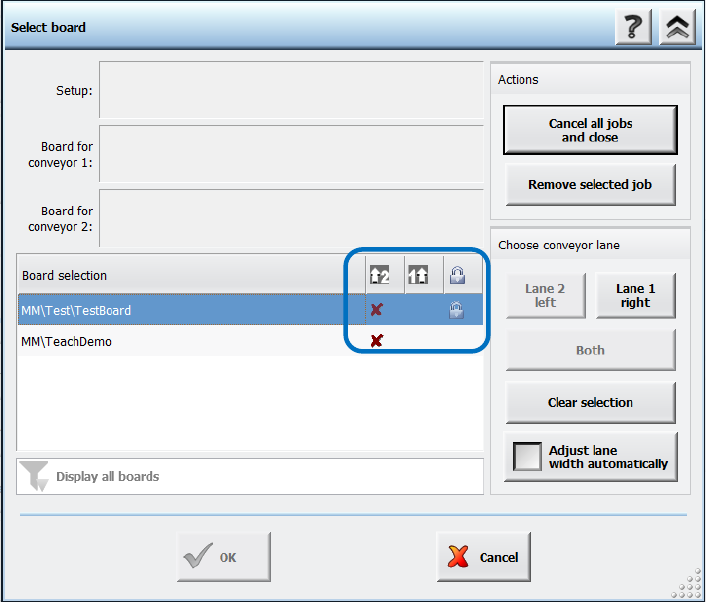
The respective board has to be accordingly marked in SIPLACE Pro. For such boards a lock icon is
then displayed in a separate column in the Select Board dialog on the station software GUI. There
is also a button with which the board can be deleted from the station.
Figure 10-24: Permanent program type
Additionally, a filter can be set to display all items or only non-permanent or permanent items.
10.13.4 Placement Head Verification
Additionally to the C&P20 A, C&P20 M, C&P20 P and CPP placement heads, the Twin Head can
now also be verified within the Placement head verification.
10.13.5 Camera Verification – New Term
Camera verification has been introduced as a new term. The camera verification is performed
with the FCCS (Field Camera Calibration System) tool.
The entry point for the camera verification has been moved from the Service tool to the
Verification view and can be accessed at the Machine service activity level. The button is also
visible for lower activity levels.
Restrictions
No support for checking 3D Coplan sensors.
Station Software 7xx to 714.0 (R20-2) / Feature Description 11/2020 Edition
200
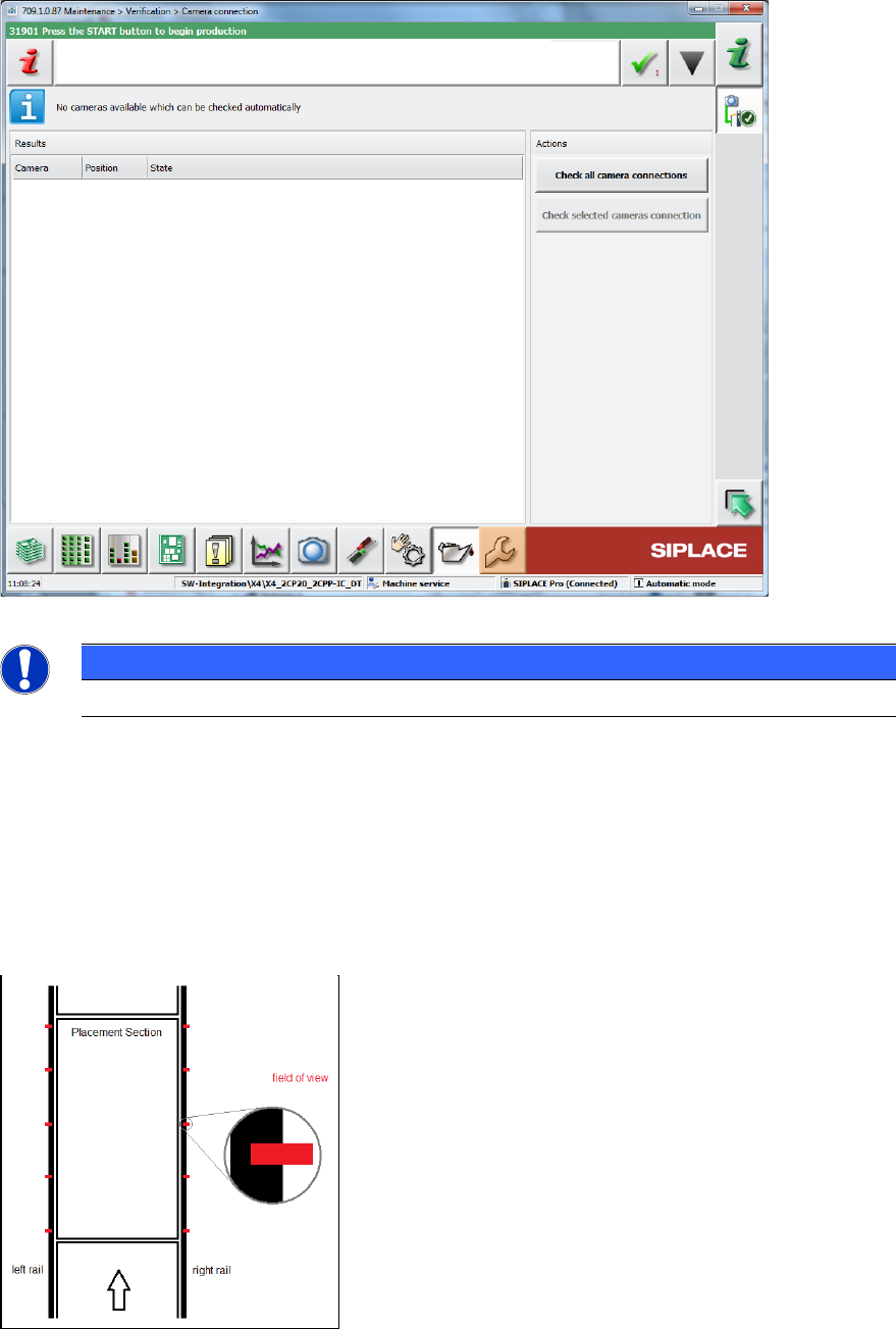
10.13.6 Camera Connections – Checking Gig E Interface
A new GUI dialog will provide information about the current health states of permanently installed
Gig E cameras and all intermediate stations.
Figure 10-25: Checking camera connections
NOTICE
This feature does not support checking Coplan sensors.
10.13.7 Conveyor Rail Verification
Compatible mode: Complete
With the Conveyor rail verification button in the Verification view, the parallelism of the conveyor
rails can be checked. For this, several X positions per processing area (currently 5) are displayed
at the outer edges of the rails.
Figure 10-26: Displayed X positions
Station Software 7xx to 714.0 (R20-2) / Feature Description 11/2020 Edition
201
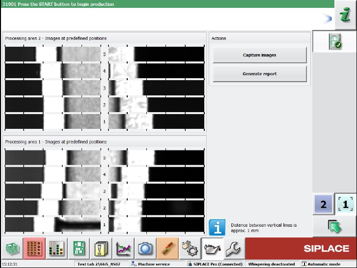
With the Capture images button, pictures are taken of the positions by the board camera.
The measurement is performed for one lane only and the results are displayed on the GUI. For
dual conveyors, there will be two independent measurements and result views. The pictures must
be inspected by the operator.
It is possible to perform the measurements with boards in the conveyor, but not during production.
The machine must be stopped before the measurements can be started.
With the Generate report button, a report can be created that contains a screenshot of the page.
Figure 10-27: Result view of a machine with two processing areas
The report is stored at the station.