00197395-03_AI_3D_Sensor-Koplan_X-Serie_S_DE_EN.pdf - 第100页
3 Installation 3.2 Preparing the Installation of the IC Camera (Type 33) 100 Assembly Instructions / Montageanleitung SIPLACE X-Series S 3D-Sensor 06/2020 Replacing the IC camera If a stationary camera is present, move t…

3 Installation
3.1 Preparing the Workplace
Assembly Instructions / Montageanleitung SIPLACE X-Series S 3D-Sensor 06/2020 99
3 Installation
3.1 Preparing the Workplace
► Switch off the machine, disconnect it from the power supply and secure it to prevent unauthor-
ized reactivation. Observe the instructions in section 1.2
"Preparatory work..." [}89].
► Remove the component trolley from locations 1 and 2.
► Remove the used tape chutes at locations 1 and 2 (see 4.1.1 "Replacing the waste tape
slide" [}137]).
See also
2 4.2.1 "Fitting the Camera" [}140]
3.2 Preparing the Installation of the IC Camera (Type 33)
NOTICE
3D coplanarity module and stationary camera
IC cameras of type 33 can only be fitted next to the 3D coplanarity module at location 2.
On a SIPLACE X2S / X3S the stationary camera is fitted at location 3. If a 3D coplanarity
module is fitted, the stationary camera must be fitted/refitted at location 2.
Perform the following tasks and refer to the appropriate assembly instructions (see below):
► Refit the stationary camera from location 3 to location 2.
► Set the DIP switch to location 2.
► Connect CAN2 to the component camera.
► Connect GigE 3 to the component camera.
Refer also to the appropriate assembly instructions:
●
Assembly instructions "SIPLACE X-Series S, SX-Series V3 stationary camera type 25/33
(GigE)" [00197710‑xx]
●
Assembly instructions "SIPLACE X-Series S - stationary camera type 25/33" [00197397‑xx]
Excerpts from these assembly manuals can be found in the annex:
●
4.2 "Excerpt from the assembly instructions "SIPLACE X-Series S, SX-Series V3 stationary
camera type 25/33 (GigE)" [00197710‑xx]" [}140]
●
4.3 "Excerpt from the assembly instructions "SIPLACE X-Series S - stationary camera type
25/33" [00197397‑xx]" [}146]
3 Installation
3.2 Preparing the Installation of the IC Camera (Type 33)
100 Assembly Instructions / Montageanleitung SIPLACE X-Series S 3D-Sensor 06/2020
Replacing the IC camera
If a stationary camera is present, move the camera from location 3 to location 2.
► Read the relevant assembly instructions (see above).
However, do not refit the camera yet.
Observe the following points in particular:
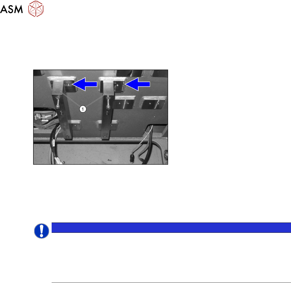
Fig.11: Spacer
► Fit the spacer plates(1) to the left posi-
tion, as the space is needed for the 3D
coplanarity module.
Camera coding
The camera needs to be re-encoded accordingly:
► Remove the lighting unit and the cover from the camera.
► Set the DIP switch (1) at the camera, according to the configuration and DIP switch type.
NOTICE
Coding the DIP switch
► The ending is based on the location and not on the gantry.
► IC cameras of type 33 up to version 07 are equipped with an 8-pin DIP switch. IC
cameras of type 33 from version 07 are equipped with a 6‑pin DIP switch.
► More details can be found in the relevant assembly instruction manual itself (see
above).
Fitting the IC camera
The camera is fixed on two spacer plates, which have already been screwed to the screw fixing
points on the machine base.
► Read the relevant assembly instructions (see above).
However, do not refit the camera yet.
3 Installation
3.3 Fastening the 3D Coplanarity Module
Assembly Instructions / Montageanleitung SIPLACE X-Series S 3D-Sensor 06/2020 101
3.3 Fastening the 3D Coplanarity Module
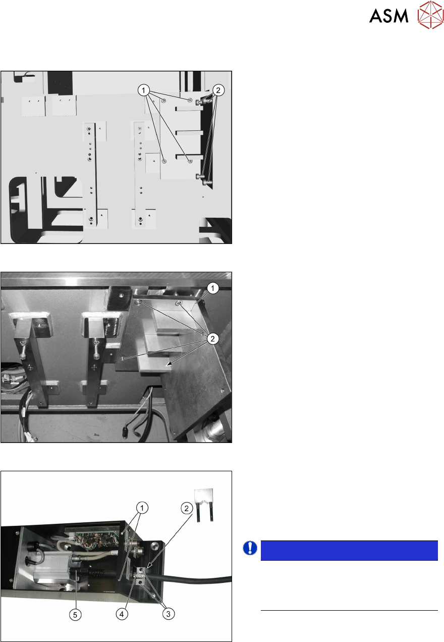
Fig.12: Screws
Screws required:
1. Four screws M6x12
2. Four fitting screws M6x12
Fig.13: Fitting the holder
► Place the holder (1) onto the machine
base, next to the camera blocks which
were moved.
► Screw the holder into place with the
four M6x12 (2)
screws.
Fig.14: Fitting the camera link cable
► Remove the screws (1) fastening the
cover on the electronics and remove
the cover.
► Remove the screws(3) for the shield
clamp(2)
.
NOTICE!
The strain relief parts on the 3D co-
planarity module are asymmetrical.
The narrower side must point to the 3D
coplanarity module.
.
► Connect the bare end of the camera
link cable(4)
to the 3D coplanarity
sensor at the 3PY terminal and secure
it to the connector with the two
screws(5)
.
► Screw the shield clamp(2) to the bare
end of the cable.