00197395-03_AI_3D_Sensor-Koplan_X-Serie_S_DE_EN.pdf - 第130页
3 Installation 3.17 Commissioning with SW 70x 130 Assembly Instructions / Montageanleitung SIPLACE X-Series S 3D-Sensor 06/2020 3.17.3 Calibrating the 3D Coplanarity Module Fig.74: Calibration tool ► Remove the calibrat…
3 Installation
3.17 Commissioning with SW 70x
Assembly Instructions / Montageanleitung SIPLACE X-Series S 3D-Sensor 06/2020 129
From SW 712.x
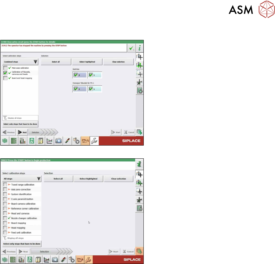
Fig.72: Calibration (combined steps)
Fig.73: Calibration (all steps)
You can choose between Combined steps
and All steps.
The procedure for All steps is described
below.
► Go to Select calibration steps and se-
lect All steps
.
► Choose Heads and cameras.
► On the next page, select the gantries
on which the heads to be calibrated are
located and then click on the Next
but-
ton.
Follow the instructions on the next pages:
► The next step is to check the calibration
conditions (nozzle, calibration tool etc.).
Follow the instructions provided.
After this step, the calibration will begin. All
required intermediate steps (head height
etc.) will be performed automatically.
3 Installation
3.17 Commissioning with SW 70x
130 Assembly Instructions / Montageanleitung SIPLACE X-Series S 3D-Sensor 06/2020
3.17.3 Calibrating the 3D Coplanarity Module
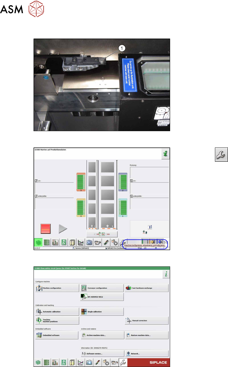
Fig.74: Calibration tool
► Remove the calibration tool and place
the supplied "calibration jig coplan
module" [00315365S-xx] on the center
of the pocket (1)
.
► Prerequisite: Pick up the calibration
nozzle.
Twin: 517
CPP: 2057
Fig.75: Start screen
► Select the button.
ð The Configure, update and cali-
brate the machine view will be
shown.
Fig.76: Automatic calibration
► Select the Automatic calibration but-
ton.
ð The Automatic calibration view
will be shown.
3 Installation
3.17 Commissioning with SW 70x
Assembly Instructions / Montageanleitung SIPLACE X-Series S 3D-Sensor 06/2020 131
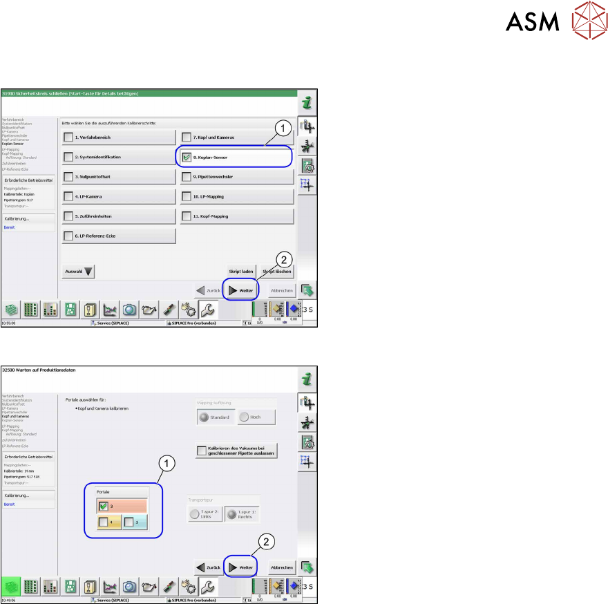
Up to SW 711.x
Fig.77: Coplanarity sensor
► Select the Coplan Sensor(1) button.
► Select the Next(2) button.
ð The Coplan Sensor view will be
shown.
Fig.78: Gantry selection
► Select the relevant gantry (1).
► Select the Next(2) button.
ð The calibration will be started.
► Once the calibration values are dis-
played, click on the Accept
button.
► Remove the calibration jig.