00197395-03_AI_3D_Sensor-Koplan_X-Serie_S_DE_EN.pdf - 第89页
1 Introduction 1.2 Preparatory work... Assembly Instructions / Montageanleitung SIPLACE X-Series S 3D-Sensor 06/2020 89 1.2 Preparatory work... Purpose and scope Before performing any preventive maintenance work, convers…
1 Introduction
1.1 Safety instructions
88 Assembly Instructions / Montageanleitung SIPLACE X-Series S 3D-Sensor 06/2020
1.1.8 Safety instructions for the sensor of the coplanarity module
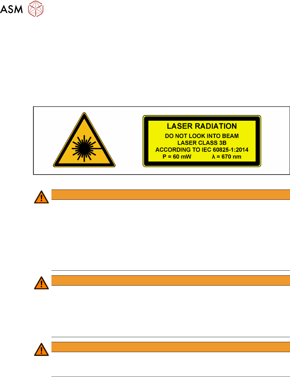
The sensor works with a semiconductor laser of wave length 670 nm (visible/red).
The maximum optical output performance is 60 mW.
The sensor is classified as laser class 3B.
► When operating the sensor, always follow the relevant regulations on "Radiation safety for
laser equipment" according to IEC60825‑1:2014 and the "Laser Radiation" (DGUV Direction
11) accident prevention regulation applicable in Germany.
► Also follow the accident prevention regulations applicable in your country.
The following information plates are attached to the front and back of the sensor housing:
Fig.3: Identification of laser class 3B for the sensor
WARNING
The laser radiation is a danger to the eye.
The accessible laser radiation is a danger to the eye and, in special cases, also to the skin.
Exposure to direct radiation or reflected radiation of class 3B lasers (medium performance)
is a danger to the eye. In the upper performance area, lasers can cause damage to the
skin.
► Never look directly into the laser beam.
► The 3D coplanarity module is secured and built into the machine in such a way that,
when used as prescribed (shortterm radiation), the accessible radiation complies with
laser class 2 and as a result is no danger to the eye.
WARNING
Encapsulated class 2 laser device
When fitted, the placement machine is classified as a so-called "encapsulated" class 2
laser device.
► The 3D sensor is integrated into the emergency STOP circuit.
► Do not disable the emergency STOP circuit!
► The 3D sensor may only be operated inside the placement machine!
WARNING
Repair and Service
► For repair and service, always return the sensors to ASM Assembly Systems GmbH &
Co. KG.
1 Introduction
1.2 Preparatory work...
Assembly Instructions / Montageanleitung SIPLACE X-Series S 3D-Sensor 06/2020 89
1.2 Preparatory work...
Purpose and scope
Before performing any preventive maintenance work, conversion work or service work, a procedure
of locking and tagging must be followed and warning signs must be attached if not stated other-
wise. If you do not need to switch off the machine, this will be clearly stated.
The procedure, when followed, correctly eliminates the possibility of an employee being injured.
NOTICE
Additional safety measures
This procedure represents the minimum lock out and tag out requirements for the machine
during preventive maintenance work and service work. Any additional safeguards needed
to complete work safely can be specified by facilities supervision, the safety officer, the
safety committee and the health department.
Description
Whenever it becomes necessary to isolate, control and release energy, the following procedure is
to be followed.
► Notify all affected employees.
► Switch off the machine and all additional devices. Carry out all normal stopping procedures:
ð Press the stop button.
ð Shut down the station computer.
ð Switch off the machine using the main switch.
► Isolate the machine from all its energy sources:
ð Shut off the compressed air supply.
ð Shut off the main power supply.
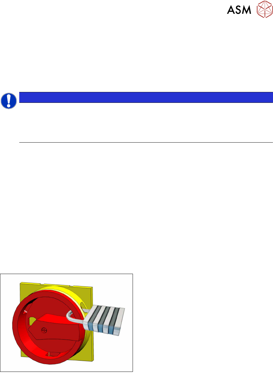
► Lock out the machine.
ð Attach a lock wherever possible.
Fig.4: Attaching a padlock to the main power switch
Secure main switch
► Secure the main switch with a padlock.
1 Introduction
1.2 Preparatory work...
90 Assembly Instructions / Montageanleitung SIPLACE X-Series S 3D-Sensor 06/2020
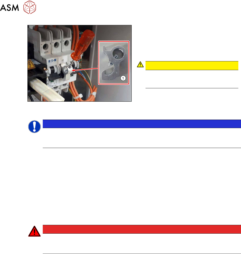
Fig.5: Attaching the lockout attachment Z-IS/SPE-1TE
[03123101-xx] (replaces:[03121545‑xx])
Alternative: secure the circuit breaker
The lockout attachment can prevent the
machine from being switched on inadvertently.
► Switch off the machine.
► Set the circuit breaker to OFF.
CAUTION!
The lockout attachment may only be
attached when the machine is switched
off!
.
► Attach the lockout attachment(1) to the
circuit breaker.
► Secure the circuit breaker with a padlock.
NOTICE
Lockout attachment in the service box of your machine
On machines that are delivered from June 2016, the lockout attachment [03123101‑xx] is
located in the service box.
► Attaching warning signs:
If a machine can be locked, it must be.
However, there are situations where energy isolating devices cannot accommodate locks. In
these cases, the energy isolating devices must be tagged appropriately to warn employees
that the machine is currently de-energized for service purposes. The tag or label must be se-
curely fastened, it must be placed in a position visible to all and it may only be removed by the
person who attached it.
► Release of stored energy:
Energy stored as compressed air in the compressed air supply or electrical energy stored in
electrolytic capacitors must be released by appropriate means.
After switching off the machine, wait until the voltages have discharged and the compressed
air has released, so that work can be performed without any risk.
DANGER
Checking for absence of voltage!
► Before you start working, check the power supply for absence of voltage and observe
the waiting times!
► Testing the lock out:
The lock can be easily tested by pressing the Start button.
The following steps must be taken to restore the machine to operation.
► Check the workspace. Authorized employees should remove all of their tools and reinstall all
safety features.
► Notify all affected employees.
► Before removing even one lock or tag, inform all workers in the affected area that the machine
is going to be restarted.
► Remove all locks/tags.
Every authorized employee must remove his own lock and shut it away.
► Switch on the machine. Make sure that authorized staff check the equipment in operation to
ensure that all repairs were performed correctly.