00197395-03_AI_3D_Sensor-Koplan_X-Serie_S_DE_EN.pdf - 第110页
3 Installation 3.7 Connecting the Cable to the (M)GCU 110 Assembly Instructions / Montageanleitung SIPLACE X-Series S 3D-Sensor 06/2020 3.7.2 Overview of MGCUs Fig.31: Overview of MGCUs on X2 S
3 Installation
3.7 Connecting the Cable to the (M)GCU
Assembly Instructions / Montageanleitung SIPLACE X-Series S 3D-Sensor 06/2020 109
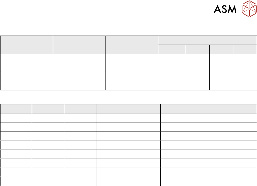
DIP switch (gantry ID)
Switch Status Signal name Description
GCU1 GCU2 GCU3 GCU4
S1.1 ON/OFF Gantry_ID_0 OFF ON OFF ON
S1.2 ON/OFF Gantry_ID_1 OFF OFF ON ON
S1.3 ON/OFF Gantry_ID_2 OFF OFF OFF OFF
S1.4 ON/OFF Portal_ID_3 OFF OFF OFF OFF
LEDs
LED Color Status Signal name Description
H1 RD ON LED_ERROR Error display
H2 GN ON A1_LED_PM_ON_N Power module activated, axis 1
H3 GN ON A2_LED_PM_ON_N Power module activated, axis 2
H4 GN ON A1_LED_END End position signal, axis 1
H5 GN ON A2_LED_END End position signal, axis 2
H6 GN ON LED_READY Ready
H7 GN ON P24V +24VDC
H8 GN ON P5V +5VDC
3 Installation
3.7 Connecting the Cable to the (M)GCU
110 Assembly Instructions / Montageanleitung SIPLACE X-Series S 3D-Sensor 06/2020
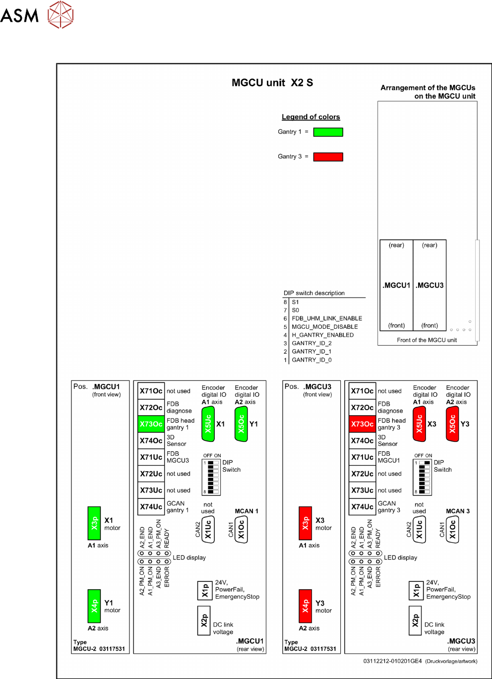
3.7.2 Overview of MGCUs
Fig.31: Overview of MGCUs on X2 S
3 Installation
3.7 Connecting the Cable to the (M)GCU
Assembly Instructions / Montageanleitung SIPLACE X-Series S 3D-Sensor 06/2020 111
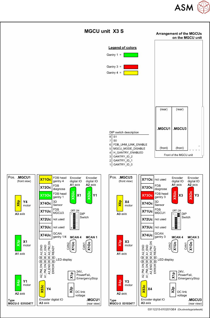
Fig.32: Overview of MGCUs on X3 S