00197395-03_AI_3D_Sensor-Koplan_X-Serie_S_DE_EN.pdf - 第86页
1 Introduction 1.1 Safety instructions 86 Assembly Instructions / Montageanleitung SIPLACE X-Series S 3D-Sensor 06/2020 Fig.1: Power supply unit (SIPLACE X-SeriesS, SMPS) 1. Main switch (S1) 2. Main power supply cable …
1 Introduction
1.1 Safety instructions
Assembly Instructions / Montageanleitung SIPLACE X-Series S 3D-Sensor 06/2020 85
1.1.3 Safety instructions for the power supply (with SMPS)
NOTICE
Validity
This section applies to the following machine types with SMPS (Switched Mode Power
Supply):
► SIPLACE X-Series S from serial no. Hxxxx
Residual voltages and discharge times in the machine
If the emergency stop button is pressed or the machine is switched off, the 300V~ link voltage for
the gantry axes and the 160V~ link voltage for the star axes are reduced to harmless residual
voltages in a very short time.
DANGER
Dangerous voltages!
The machine is supplied with 3 x 380 V~ to 3 x 415 V ± 10 %, 50/60 Hz or optional with 3 x
200 V~ to 3 x 220 V~ ± 10 %; 50/60 Hz mains voltage. This means that some parts of the
system carry potentially lethal voltages - even when it is switched off at the main power
switch and the power plug is unplugged.
Death, serious injury or considerable damage may result if these machines are handled
incorrectly.
► Always follow the applicable accident prevention and DIN regulations (particularly EN
60204, part 1 or IEC 60204, part 1) and the applicable regulations in your own coun-
try.
► The covers of the power supply unit may only be opened by appropriately qualified
and trained personnel.
► Please observe the safety instructions in the user manual for all work!
► Before you start working on the power supply, check it for absence of voltage and
observe the waiting times!
CAUTION
Loss of data!
To avoid losing data, assess the following criteria before switching off your machine (apart
from in emergencies):
► Has the machine finished transmitting machine, setup and panel data.
► Has the machine finished processing the PCB.
► Has the machine completed the run-up phase.
Machine switched off at the main switch, but still connected
DANGER
Risk of death by voltages!
Death, serious injury or considerable damage may result if these machines are handled
incorrectly.
The following components still carry potentially lethal voltages on the power supply even if
the main power switch is switched off:
► Main power supply cable connection terminals
► L1, L2, and L3 of the main switch S1
► Service socket X98 (if present)
► The contactor safety breaker (CBS) still carries voltage for five minutes after switching
off at the main switch.
► The color of all individual wires which still carry potentially lethal voltages even if the
main power switch is switched off is orange.
1 Introduction
1.1 Safety instructions
86 Assembly Instructions / Montageanleitung SIPLACE X-Series S 3D-Sensor 06/2020
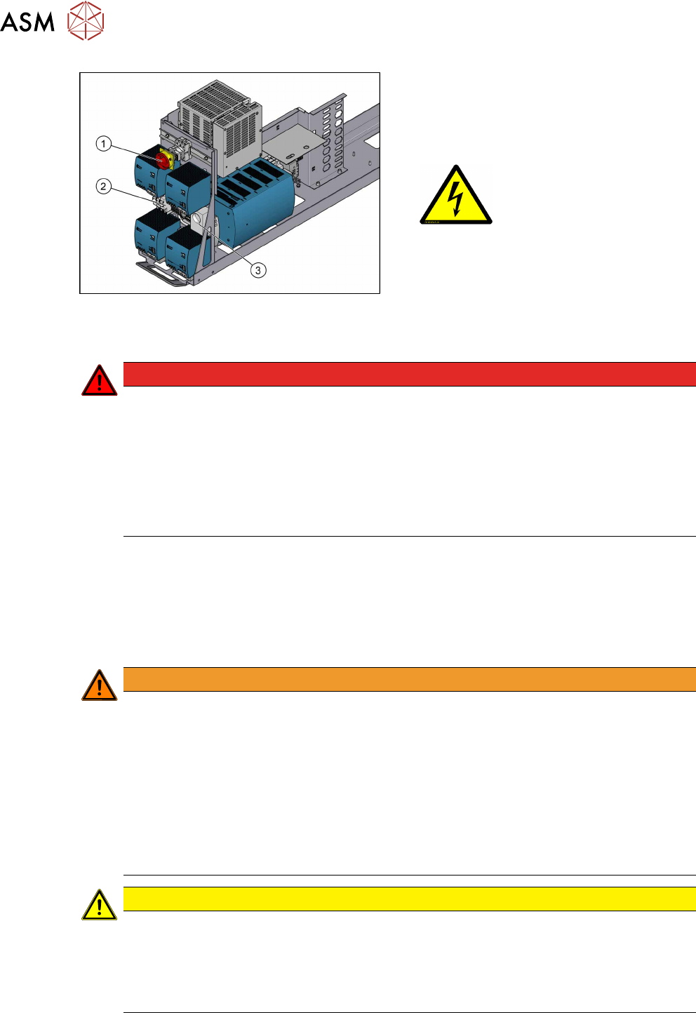
Fig.1: Power supply unit (SIPLACE X-SeriesS, SMPS)
1. Main switch (S1)
2. Main power supply cable connection ter-
minals (X95) for the power supply cable
3. Service socket X98
(if present)
Machine switched off at the main power switch and disconnected
DANGER
Hazardous voltages in the power supply unit!
The power supply unit houses components (capacitors) that can carry hazardous voltages
for about five minutes after the machine has been switched off and the power plug has
been unplugged.
► Wait at least five minutes before your start working on the power supply unit.
► Work on the power supply and the contactor safety breaker (CSB) must only be car-
ried out by service engineers of ASM Assembly Systems GmbH & Co. KG or by
machine owner service engineers who have been trained by ASM.
Compressed air conditions in the machine after switching off at the main switch
When the machine is switched off at the main power switch or if the power supply fails, the electric-
ally-controlled main valve of the compressed air unit closes. The pressure will drop to 0 MPa
(0bar) within five seconds.
1.1.4 Safety instructions for work on the cutting device
WARNING
Risk of injury when working near the cutter.
When working in the area of the tape cutter, move the component trolley out of the machine
and disconnect the machine from the mains supply and the compressed air supply.
► Wait until the operating pressure has dropped to 0 MPa.
► Pull one of the thinner hoses off the Y distributor on the cutter, to vent the pneumatic
lines and the cutter (see Venting compressed air at the cutter).
► After completing work to the cutter, you will need to connect the hose again.
► Always secure the machine against unauthorized reactivation.
► Do not reach into the tape cutter.
CAUTION
Risk of injury when performing service work on the tape cutter.
Never support the tape cutter on your body, e.g. on your knees or thighs. Do not place your
feet under the tape cutter.
► Wear appropriately thick protective gloves.
► Only hold and carry the cutter on the outer left and righthand parts.
1 Introduction
1.1 Safety instructions
Assembly Instructions / Montageanleitung SIPLACE X-Series S 3D-Sensor 06/2020 87
1.1.5 Safety instructions for the gantry
CAUTION
Moving the gantry can damage the placement head.
When moving the gantry, observe the following:
► NEVER move the gantry by pushing with your hands against the placement head.
► NEVER push the gantry while the Z axis is lowered.
1.1.6 Safety instructions on hazardous materials
CAUTION
Observe the safety data sheets
Observe the applicable safety data sheet, when handling hazardous materials (e. g. Loctite
241, ethanol).
1.1.7 Classification of the optical systems
1.1.7.1 Classification of the whole machine
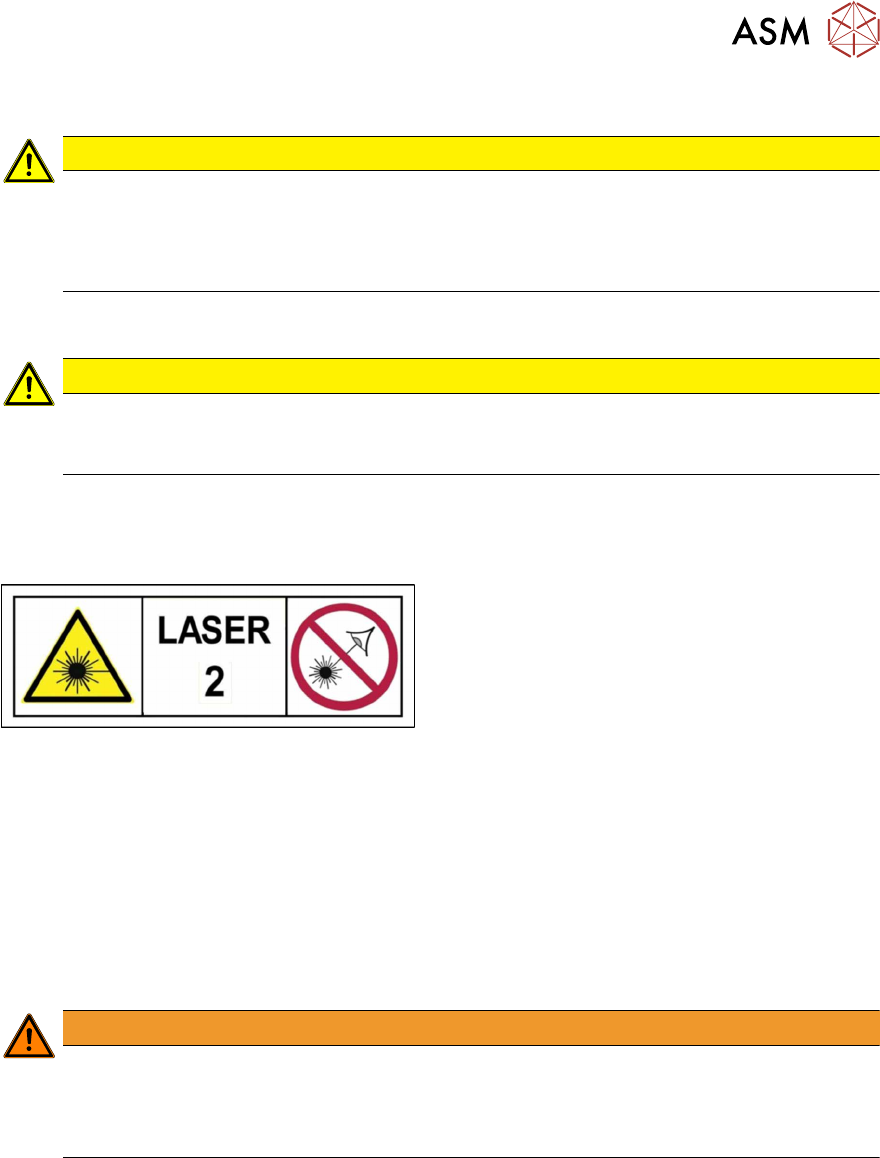
Fig.2: Laser class 2
The ready-to-operate overall machine is assigned
to laser class°2.
The laser classes are determined according to
DIN EN 60825-1:2014.
1.1.7.2 Laser classification
The following modules are assigned to laser class 2:
●
Component sensor on the SpeedStar
●
Component sensor on the MultiStar
●
Laser light barriers at the board conveyor
1.1.7.3 Classification of the camera systems
WARNING
LEDs
The camera illumination systems are fitted with light LEDs. These are assigned to risk
group 1 according to IEC 62741:2006.
► Do not look into beam!