00197395-03_AI_3D_Sensor-Koplan_X-Serie_S_DE_EN.pdf - 第140页
4 Appendix 4.2 Excerpt from the assembly instructions "SIPLACE X-Series S, SX-Series V3 stationary camera type 25/33 (GigE)" [00197710‑xx] 140 Assembly Instructions / Montageanleitung SIPLACE X-Series S 3D-Sens…
4 Appendix
4.1 Excerpts from the Service Manual
Assembly Instructions / Montageanleitung SIPLACE X-Series S 3D-Sensor 06/2020 139
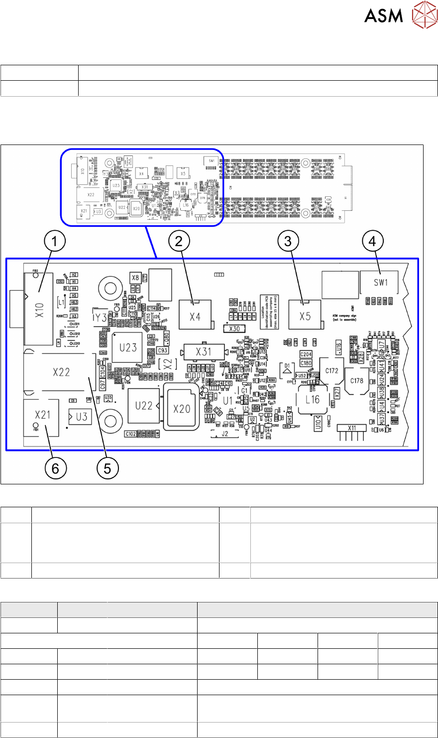
4.1.3 Vision LED Controller VLC25/33 GigE DTC
03117981-xx Vision LED Controller VLC33 GigE DTC
03117587-xx Vision LED Controller VLC25 GigE DTC
These two circuit boards are in principle identical. The VLC25 board however, also has the con-
nectors X21 and X22
The circuit boards are part of the stationary camera SST25/33 GigE.
Fig.95: Vision LED Controller VLC25 GigE DTC [03117587-xx]
1 CAN bus 2 X4: Cable for power supply
3 X5: Cable for power supply, bridge to FC
camera
(Not used in TX-Series)
4 DIP switch SW1 (see below)
5 Connector X22 (VLC25 only) 6 Connector X21 (VLC25 only)
DIP switch S1 [03117587-xx] [03117981-01]
Switch State Signal name Description
S1.1 OFF VCU_CODE OFF: normal operation, ON: Reset
Location 1 Location 2 Location 3 Location 4
S1.2 ON/OFF GANTRY_ID_0 *) OFF ON OFF ON
S1.3 ON/OFF GANTRY_ID_1 *) OFF OFF ON ON
S1.4 OFF SMD_LED OFF: standard LED, ON: SMD LED
S1.5 OFF CAN_H OFF: with CAN terminator
ON: without CAN terminator
S1.6 ON/OFF CAN_GROUP ON: IC camera , OFF: FC camera
*) Set the location at which the stationary camera is fitted.
4 Appendix
4.2 Excerpt from the assembly instructions "SIPLACE X-Series S, SX-Series V3 stationary camera type 25/33
(GigE)" [00197710‑xx]
140 Assembly Instructions / Montageanleitung SIPLACE X-Series S 3D-Sensor 06/2020
4.2 Excerpt from the assembly instructions "SIPLACE X-
Series S, SX-Series V3 stationary camera type 25/33
(GigE)" [00197710‑xx]
The following chapter shows excerpts from the assembly instructions. More details can be found in
the assembly instruction manual itself.
4.2.1 Fitting the Camera
Configurations
IC cameras of type 33 can be installed at all four locations (exception: no installation at PA1 pos-
sible at SIPLACE X4i S).
FC cameras of type 25 can only be installed at locations 2 and 3, only in combination with IC cam-
era type 33.
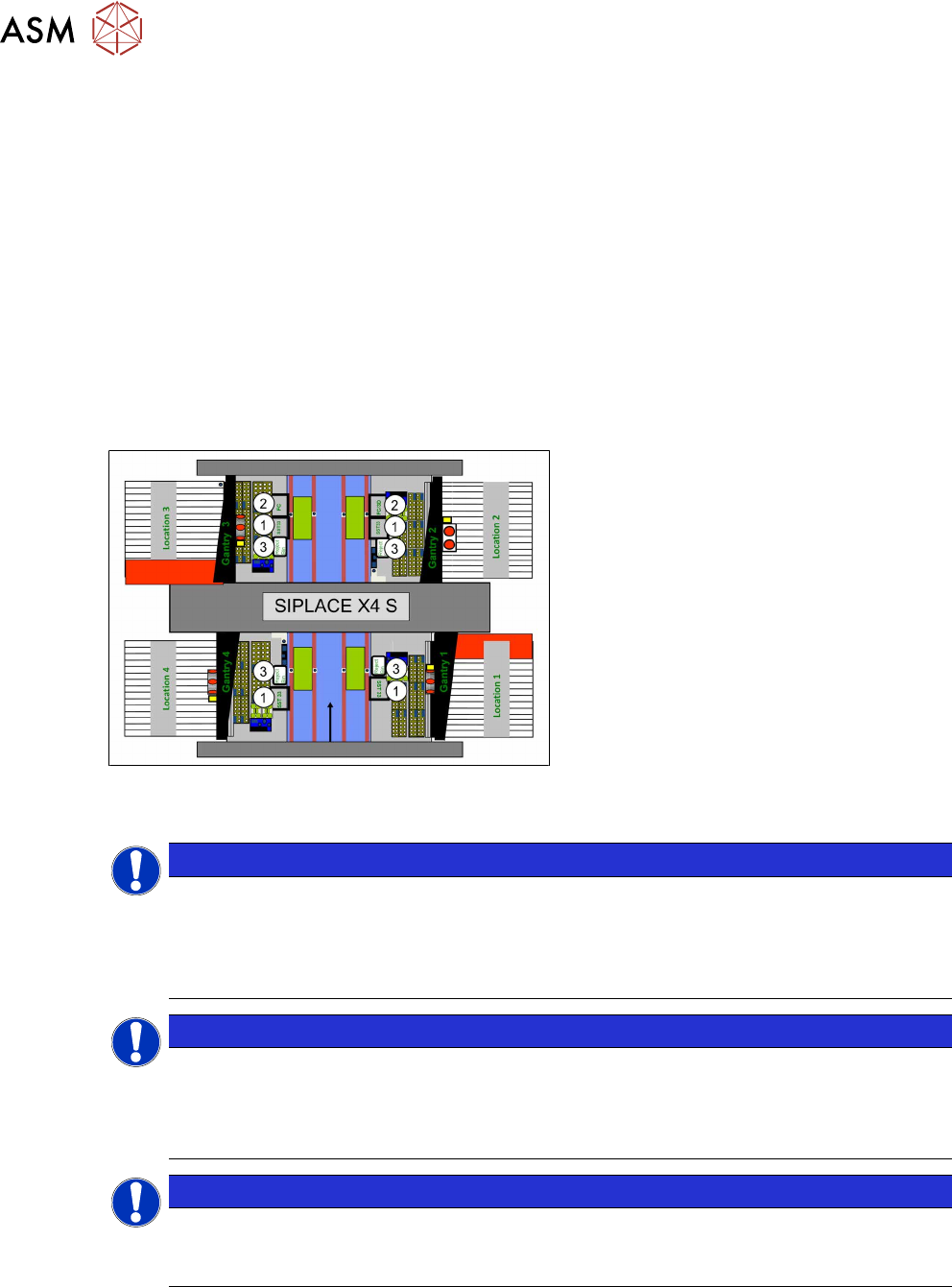
Fig.96: Installation position of cameras (using example of
SIPLACE X4 S)
1. IC camera, type 33
2. FC camera / 3D coplan (location2
only)
3. Component reject bin
NOTICE
SIPLACE Twin
The FC camera and the 3D coplan module are only possible together with a SIPLACE
Twin. Only one of these options can be fitted at the same location, meaning that either the
FC camera or the 3D coplan module can be used and only in combination with an IC cam-
era.
NOTICE
SIPLACE CPP
► A 3D coplan module can be fitted together with an IC camera and a SIPLACE CPP.
► The combination of an IC camera with a FC camera and a SIPLACE CPP is not pos-
sible.
NOTICE
3D coplan
If a 3D coplanarity is fitted, this only being possible at location 2, the stationary camera (IC
camera) must also be fitted at location 2.
4 Appendix
4.2 Excerpt from the assembly instructions "SIPLACE X-Series S, SX-Series V3 stationary camera type 25/33
(GigE)" [00197710‑xx]
Assembly Instructions / Montageanleitung SIPLACE X-Series S 3D-Sensor 06/2020 141
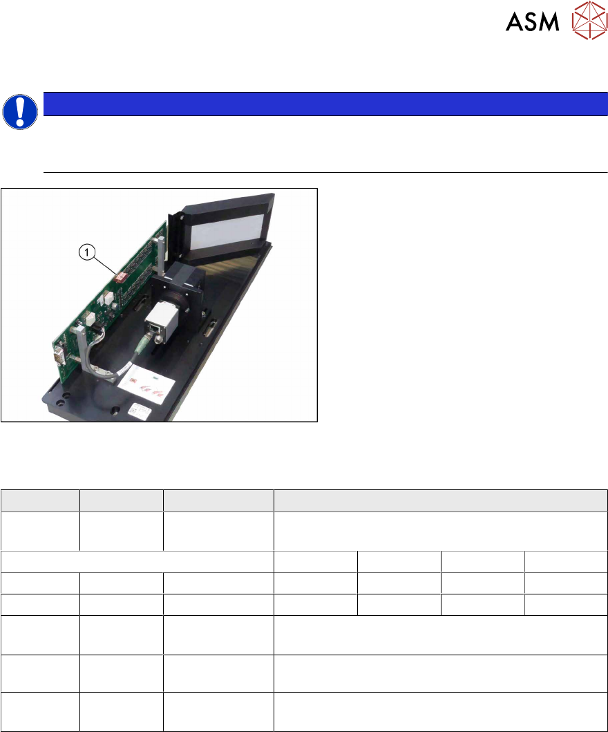
4.2.1.1 Adjusting the Camera Jumper Setting
NOTICE
Replacing the camera housing when there is more than one camera
When fitting the cover and the lighting unit, make sure that this is not confused with the one
for a different camera.
Fig.97: DIP switch (example with camera type 33 shown)
► Set the DIP switch (1) on the camera.
► Make a note of the jumper setting on
the relevant label on the camera hous-
ing.
DIP switch S1 for SST25 and SST33
Switch Status Signal name Description
S1.1 OFF VCU_CODE OFF: normal operation
ON: Reset
Location 1 Location 2 Location 3 Location 4
S1.2 ON/OFF *) PORTAL_ID_0 OFF ON OFF ON
S1.3 ON/OFF *) GANTRY_ID_1 OFF OFF ON ON
S1.4 OFF SMD_LED OFF: standard LED
ON: SMD LED
S1.5 OFF CAN_H OFF: with CAN terminator
ON: without CAN terminator
S1.6 ON/OFF CAN_GROUP OFF: FC camera
ON: IC camera
*) Set the location at which the stationary camera is fitted.
See also
2 4.3.1.1.1 "Coding the DIP Switch (8 Pin)" [}147]
2 4.3.1.1.2 "Coding the DIP Switch (6 Pin)" [}148]
4.2.1.2 Fitting the IC Camera Type 33
The camera is fixed at two spacer plates, which have already been screwed to the screw fixing
points on the machine base.
The procedure for fitting these spacer plates and for fixing the cameras is in principle the same at
all locations. Any differences are indicated in the following section.
► Before installation, make sure that the jumper setting for the camera to be fitted is correct (see
4.3.1.1
"Adjusting the Camera Jumper Setting" [}147]).
See also
2 4.3.1.2.2 "IC Camera Type 33: Fixing the Camera Module" [}152]