00197395-03_AI_3D_Sensor-Koplan_X-Serie_S_DE_EN.pdf - 第102页
3 Installation 3.4 Sticking the Laser Warning Labels Into Place 102 Assembly Instructions / Montageanleitung SIPLACE X-Series S 3D-Sensor 06/2020 Fig.15: Inserting the fitting screws ► Insert the top fitting screws M8x1…
3 Installation
3.3 Fastening the 3D Coplanarity Module
Assembly Instructions / Montageanleitung SIPLACE X-Series S 3D-Sensor 06/2020 101
3.3 Fastening the 3D Coplanarity Module
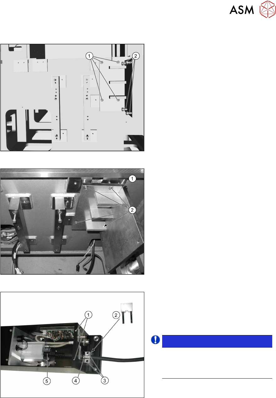
Fig.12: Screws
Screws required:
1. Four screws M6x12
2. Four fitting screws M6x12
Fig.13: Fitting the holder
► Place the holder (1) onto the machine
base, next to the camera blocks which
were moved.
► Screw the holder into place with the
four M6x12 (2)
screws.
Fig.14: Fitting the camera link cable
► Remove the screws (1) fastening the
cover on the electronics and remove
the cover.
► Remove the screws(3) for the shield
clamp(2)
.
NOTICE!
The strain relief parts on the 3D co-
planarity module are asymmetrical.
The narrower side must point to the 3D
coplanarity module.
.
► Connect the bare end of the camera
link cable(4)
to the 3D coplanarity
sensor at the 3PY terminal and secure
it to the connector with the two
screws(5)
.
► Screw the shield clamp(2) to the bare
end of the cable.
3 Installation
3.4 Sticking the Laser Warning Labels Into Place
102 Assembly Instructions / Montageanleitung SIPLACE X-Series S 3D-Sensor 06/2020
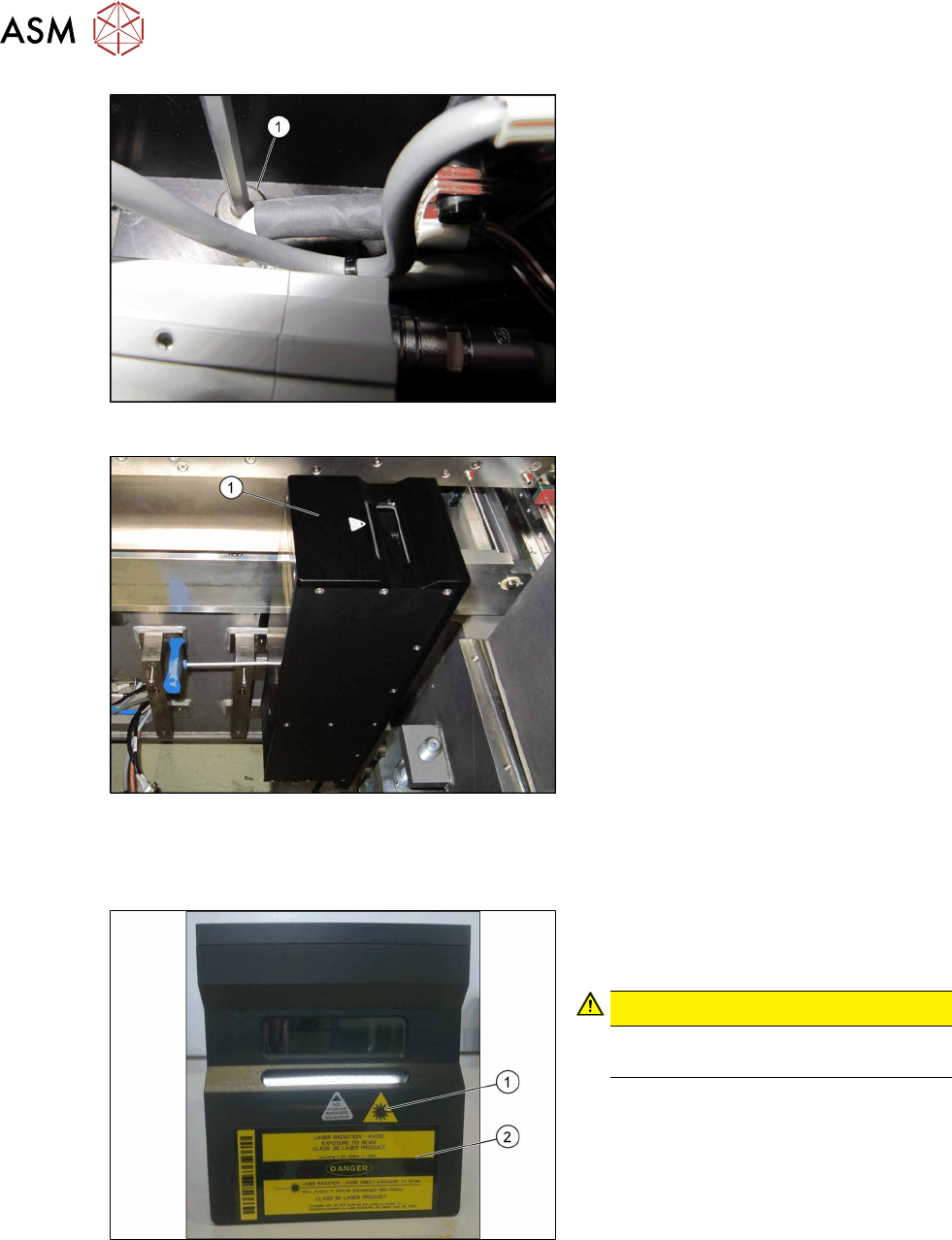
Fig.15: Inserting the fitting screws
► Insert the top fitting screws M8x12 (1),
before you fit the 3D coplanarity mod-
ule.
Fig.16: Installing the coplanarity module
► Position the 3D coplanarity module (1)
on the holder.
► Loosely insert the two lower screws.
► Tighten the screws only after all screws
have been loosely inserted.
► Fit the cover onto the 3D coplanarity
module.
3.4 Sticking the Laser Warning Labels Into Place
Fig.17: Adhesive label
► Stick both labels (1) and (2) to the top
side of the 3D coplanarity module as
shown.
CAUTION!
Now, it is clearly visible that a class 3B
laser is installed.
.
3 Installation
3.5 Removing the Station Computer
Assembly Instructions / Montageanleitung SIPLACE X-Series S 3D-Sensor 06/2020 103
3.5 Removing the Station Computer
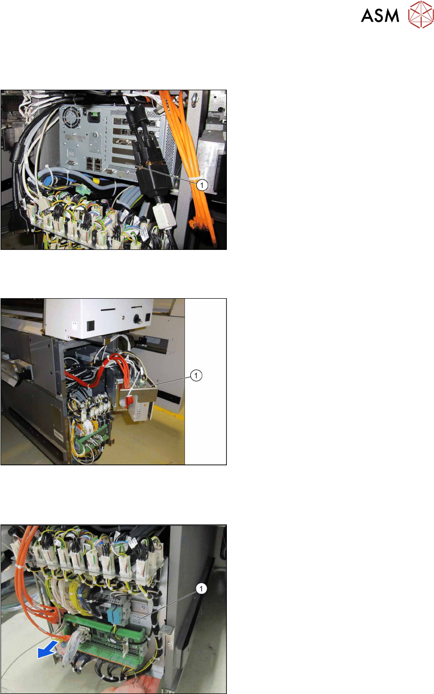
Up to serial no. Gxxxx:
Fig.18: BoxPC (example of 827C)
► Unplug all connections of the
BoxPC(1)
. If necessary, mark their po-
sitions to make clear assignment easier
later on.
► Lift the BoxPC slightly so that it is re-
leased from the Velcro fixtures.
► Pull it out towards the front.
From serial no. Hxxxx:
Fig.19: BoxPC (example of 627C)
► Unplug all connections of the
BoxPC(1)
. If necessary, mark their po-
sitions to make clear assignment easier
later on.
► Remove the screws fastening the
BoxPC and remove the BoxPC from
the machine.
3.6 Running the cable for the coplanarity computer
Fig.20: Supply door
► Open the supply door (1).