00197395-03_AI_3D_Sensor-Koplan_X-Serie_S_DE_EN.pdf - 第138页
4 Appendix 4.1 Excerpts from the Service Manual 138 Assembly Instructions / Montageanleitung SIPLACE X-Series S 3D-Sensor 06/2020 4.1.2 Vision LED driver VLT 33 This board is part of the stationary cameras SST25, SST33 a…
4 Appendix
4.1 Excerpts from the Service Manual
Assembly Instructions / Montageanleitung SIPLACE X-Series S 3D-Sensor 06/2020 137
4 Appendix
4.1 Excerpts from the Service Manual
The following chapters are excerpts from the service manual. For more information, refer to the full
service manual for your machine.
4.1.1 Replacing the waste tape slide
Parts, equipment and tools
●
Used tape chute complete [03067460-xx]
●
Allen key set
Overview
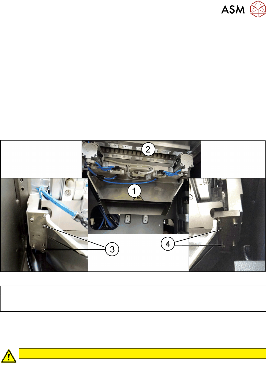
Fig.93: Waste tape slide
1 Waste tape slide 2 COT insert
3 Fastening screw for used tape chute, left 4 Fastening screw for used tape chute,
right
Removal
► Remove the screws fastening the used tape chute.
► Take the used tape chute down and out of the machine.
CAUTION
Risk of cutting
The cutter is located under the tape channel. The blades there have very sharp edges.
► Do not reach into the cutter and make sure that it is never freely accessible.
Installation
► Follow the removal instructions in reverse order for installation.
4 Appendix
4.1 Excerpts from the Service Manual
138 Assembly Instructions / Montageanleitung SIPLACE X-Series S 3D-Sensor 06/2020
4.1.2 Vision LED driver VLT 33
This board is part of the stationary cameras SST25, SST33 and SST36 (without GigE). The station-
ary cameras which can be installed will depend on the machine type.
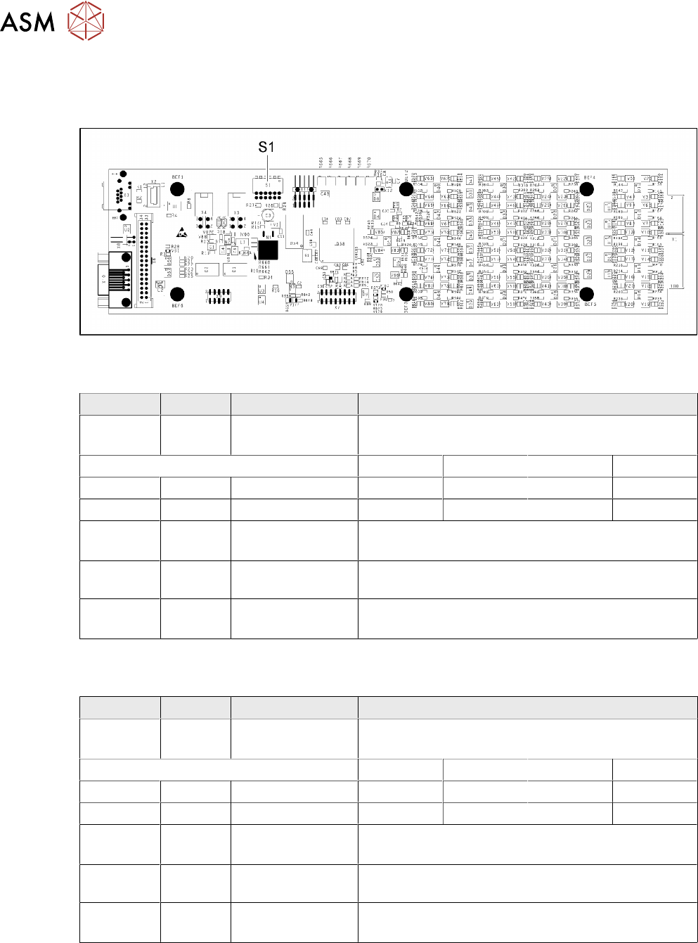
Fig.94: 03039244-03
DIP switch S1 for SST25 [03039244-03]
Switch Status Signal name Description
S1.1 OFF VCU_CODE OFF: normal operation
ON: Reset
Location 1 Location 2 Location 3 Location 4
S1.2 ON/OFF GANTRY_ID_0 *) OFF ON OFF ON
S1.3 ON/OFF GANTRY_ID_1 *) OFF OFF ON ON
S1.4 OFF SMD_LED OFF: standard LED
ON: SMD LED
S1.5 OFF CAN_H OFF: with CAN terminator
ON: without CAN terminator
S1.6 OFF CAN_GROUP OFF: FC camera
ON: IC camera
*) Set the location at which the stationary camera is fitted.
DIP switch S1 for SST33, 36 [03039244-03]
Switch Status Signal name Description
S1.1 OFF VCU_CODE OFF: normal operation
ON: Reset
Location 1 Location 2 Location 3 Location 4
S1.2 ON/OFF GANTRY_ID_0 *) OFF ON OFF ON
S1.3 ON/OFF GANTRY_ID_1 *) OFF OFF ON ON
S1.4 OFF SMD_LED OFF: standard LED
ON: SMD LED
S1.5 OFF CAN_H OFF: with CAN terminator
ON: without CAN terminator
S1.6 ON CAN_GROUP ON: IC camera
OFF: FC camera
*) Set the location at which the stationary camera is fitted.
4 Appendix
4.1 Excerpts from the Service Manual
Assembly Instructions / Montageanleitung SIPLACE X-Series S 3D-Sensor 06/2020 139
4.1.3 Vision LED Controller VLC25/33 GigE DTC
03117981-xx Vision LED Controller VLC33 GigE DTC
03117587-xx Vision LED Controller VLC25 GigE DTC
These two circuit boards are in principle identical. The VLC25 board however, also has the con-
nectors X21 and X22
The circuit boards are part of the stationary camera SST25/33 GigE.
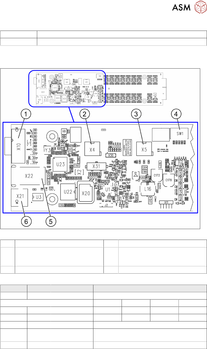
Fig.95: Vision LED Controller VLC25 GigE DTC [03117587-xx]
1 CAN bus 2 X4: Cable for power supply
3 X5: Cable for power supply, bridge to FC
camera
(Not used in TX-Series)
4 DIP switch SW1 (see below)
5 Connector X22 (VLC25 only) 6 Connector X21 (VLC25 only)
DIP switch S1 [03117587-xx] [03117981-01]
Switch State Signal name Description
S1.1 OFF VCU_CODE OFF: normal operation, ON: Reset
Location 1 Location 2 Location 3 Location 4
S1.2 ON/OFF GANTRY_ID_0 *) OFF ON OFF ON
S1.3 ON/OFF GANTRY_ID_1 *) OFF OFF ON ON
S1.4 OFF SMD_LED OFF: standard LED, ON: SMD LED
S1.5 OFF CAN_H OFF: with CAN terminator
ON: without CAN terminator
S1.6 ON/OFF CAN_GROUP ON: IC camera , OFF: FC camera
*) Set the location at which the stationary camera is fitted.