00197395-03_AI_3D_Sensor-Koplan_X-Serie_S_DE_EN.pdf - 第122页
3 Installation 3.13 Completing the Mechanical Work 122 Assembly Instructions / Montageanleitung SIPLACE X-Series S 3D-Sensor 06/2020 Fig.56: Cable ties (example of BoxPC 627C shown) ► Fasten the cable with cable ties (…
3 Installation
3.12 Installing the Coplanarity Computer
Assembly Instructions / Montageanleitung SIPLACE X-Series S 3D-Sensor 06/2020 121
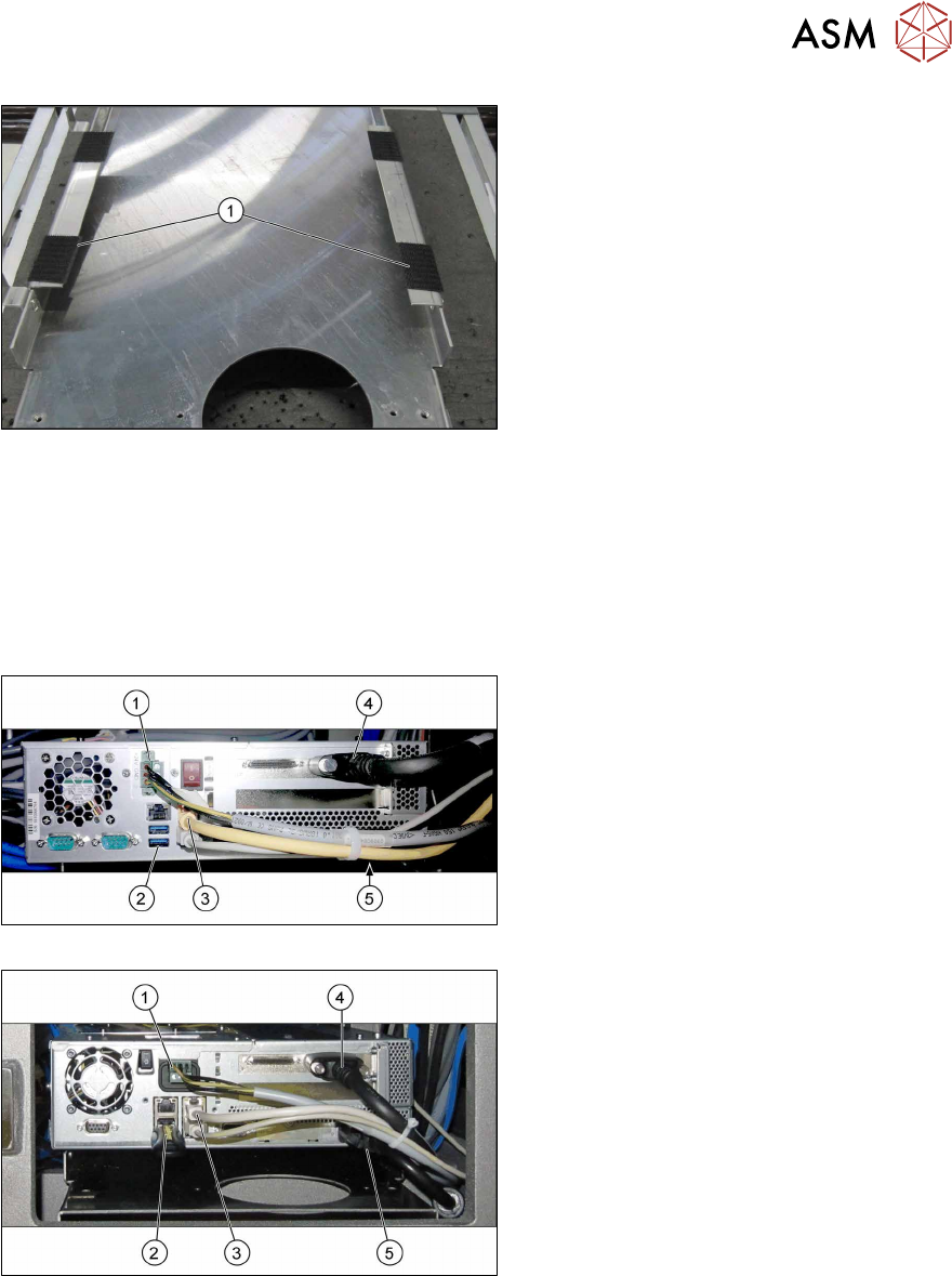
Fig.53: Velcro strips
► Pull the protective foil off the Velcro
strips and position the coplanarity com-
puter onto the brackets.
► Place the coplanarity computer onto
the brackets so that the Velcro
strips(1)
cover one another exactly.
► Reestablish all connections to the coplanarity computer.
See also:
– 3.10 "Fitting the station computer (from Hxxxx)" [}115]
– 3.11 "Installing the station computer (up to Gxxxx)" [}116]
– 4.4 "Circuit Diagrams" [}153]
► Connect the LAN cable to the station computer.
Fig.54: Cabling for coplanarity computer (BoxPC 627C)
Fig.55: Cabling for coplanarity computer (iBase)
Cables
1. Power connection: [03090848‑xx] X1qb
2. USB bottom right: USB extension cable
[03057639‑xx] X7qb
Only used for the installation of the co-
planarity computer.
USB bottom left: slot for installation me-
dium (e.g. USB stick)
3. Right LAN socket: LAN cable
[03103204‑xx] X5qb
This LAN cable connects the coplanar-
ity computer to the station computer.
4. Camera link cable from the coplanarity
computer: [03053017‑xx] X1pn
5. DVI extension cable : [03103212‑xx]
X4qb
Only used for the installation of the co-
planarity computer.
3 Installation
3.13 Completing the Mechanical Work
122 Assembly Instructions / Montageanleitung SIPLACE X-Series S 3D-Sensor 06/2020
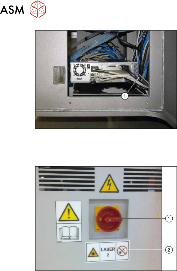
Fig.56: Cable ties (example of BoxPC 627C shown)
► Fasten the cable with cable ties(1).
3.13 Completing the Mechanical Work
Fig.57: Laser warning label
► Complete the installation of the IC cam-
era. For details, read the assembly
instructions "Stationary Camera Type
25/33" [00197397-xx].
► Fit the used tape chutes (see 4.1.1 "Re-
placing the waste tape slide" [}137]).
► As shown in the diagram, stick the
laser warning label(2)
next to the main
switch(1)
.
► Push the component trolley into the
machine.
3 Installation
3.14 Installing station software 7xx on the coplanarity computer
Assembly Instructions / Montageanleitung SIPLACE X-Series S 3D-Sensor 06/2020 123
3.14 Installing station software 7xx on the coplanarity
computer
Connecting the mouse, keyboard, monitor, and installation medium
► Switch the station computer off before you install the coplanarity computer.
► Unplug the keyboard from the station computer.
► Use the USB extension to connect the keyboard to the coplanarity computer.
► Connect the following components to the coplanarity computer:
– DVI extension to the monitor
– Keyboard to the USB extension
– Installation medium (e. g. USB stick)
Installing the operating system
► Before you install the software, you will need to define a few settings in the coplanarity com-
puter BIOS. Read the relevant installation guide.
► Start the coplanarity computer.
► Install the operating system on the coplanarity computer. This software was supplied with the
line.
Installing the station SW
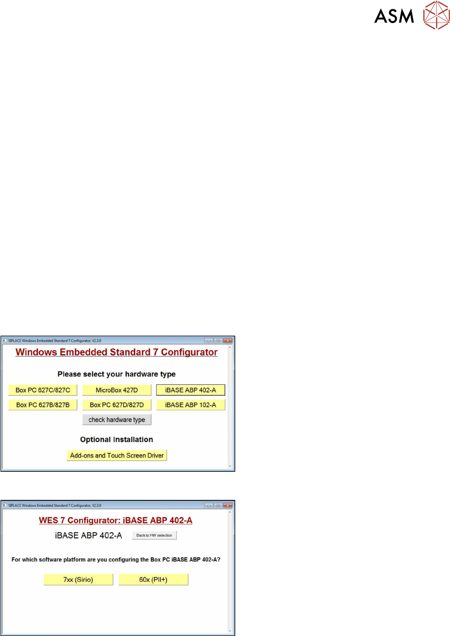
Fig.58: Configurator: Installation 1
► Log into Windows as the administrator:
Login: ASM_admin
.
► Insert the installation CD "SIPLACE
WES7 Configurator" into the CD drive.
► Start the start.hta file.
► Select your BoxPC model (e.g. iBase
ABP 402-A).
Fig.59: Configurator: Installation 2
► Select the software platform 7xx
(Sirio).