00197395-03_AI_3D_Sensor-Koplan_X-Serie_S_DE_EN.pdf - 第94页
1 Introduction 1.4 Staff qualifications and training 94 Assembly Instructions / Montageanleitung SIPLACE X-Series S 3D-Sensor 06/2020

1 Introduction
1.4 Staff qualifications and training
Assembly Instructions / Montageanleitung SIPLACE X-Series S 3D-Sensor 06/2020 93
1.3.4 Release History
Document
SIPLACE X-Series S
3D sensor
Assembly instructions
Release Amendments
02/2014 Initial release
06/2016 Amendments, supplements:
●
Safety instructions on SMPS
●
Classification of the optical systems
●
Safety instructions for the sensor of the coplanarity module
●
X module (GigE, SMPS)
●
Scope of delivery
●
Adhesive label for sensor module
●
GCU and MGCU connections
●
Installing the LAN card in the station computer
●
Installing main memory in the coplanarity computer
●
Lockout attachment
●
Cabling the coplanarity computer
●
Setting up the coplanarity computer
06/2020 Amendments, supplements:
●
Safety instructions (updated)
●
Scope of delivery (updated)
●
BoxPC ABP402-A, iBase, incl. conversion plug-in card support (supplemen-
ted)
(replaces: control computer BoxPC 627C [03094731‑xx])
●
GCU/MGCU overviews (updated)
●
Connection of LAN cable from coplanarity - to station computer (supplemen-
ted)
●
Installing station software 7xx at the coplanarity computer (updated)
●
Description of boards (supplemented)
●
Circuit diagrams for Hxxxx (updated)
1.4 Staff qualifications and training
Qualified or adequately trained personnel means that these people are familiar with the setting up,
operation and maintenance of the machine and the add-on devices and are suitably qualified, e.g.:
●
Have been trained, instructed or authorized to switch on and off, isolate, earth and identify
electrical circuits and system components in accordance with normal safety standards.
●
Have been trained or instructed in the upkeep and use of appropriate safety equipment in
accordance with normal safety standards.

1 Introduction
1.4 Staff qualifications and training
94 Assembly Instructions / Montageanleitung SIPLACE X-Series S 3D-Sensor 06/2020
2 Brief Description
2.1 Overview of Functions
Assembly Instructions / Montageanleitung SIPLACE X-Series S 3D-Sensor 06/2020 95
2 Brief Description
2.1 Overview of Functions
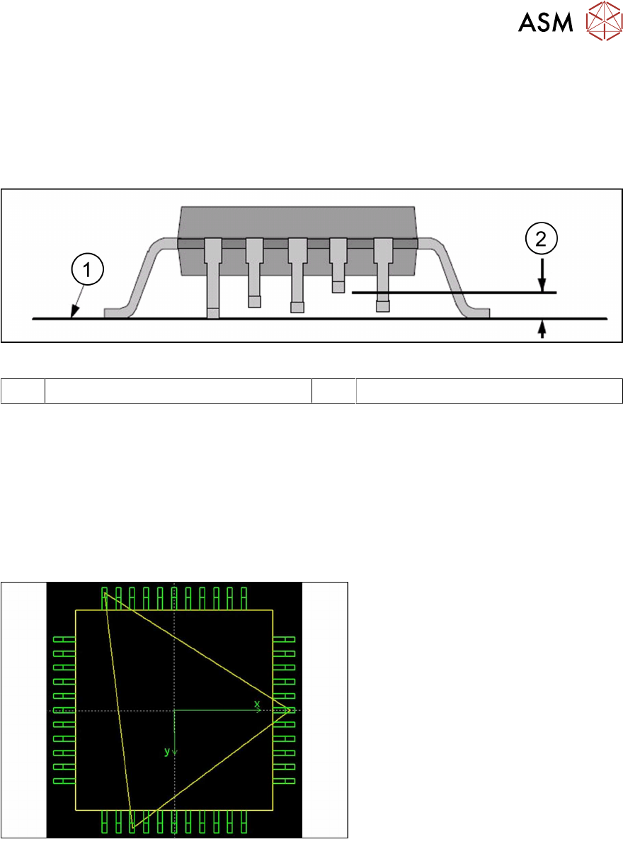
The coplanarity of a component is measured to prevent solder problems due to deformed (bent)
leads. Before placement, it is checked that all leads can reliably touch the solder paste.
Fig.7: Measuring the coplanarity of a component
1 Contact surface 2 Coplanarity deviation
The following steps are required to measure the coplanarity:
► Measuring the lead height (relative to the 3D sensor)
► Determining the contact surface (the three leads on which the component will rest when
placed onto the board).
► Determining the lead with the greatest distance to this contact surface and comparing this dis-
tance to the coplanarity threshold, which is generally somewhat less than the solder paste
thickness.
This measurement will then determine whether the component is to be placed or rejected.
Fig.8: Component contact surface
The 3D sensor operates according to the
laser triangulation principle. A laser
beam is projected onto the component
from a 45° angle. The laser beam profile
is then recorded by a camera.