00197395-03_AI_3D_Sensor-Koplan_X-Serie_S_DE_EN.pdf - 第149页
4 Appendix 4.3 Excerpt from the assembly instructions "SIPLACE X-Series S - stationary camera type 25/33" [00197397‑xx] Assembly Instructions / Montageanleitung SIPLACE X-Series S 3D-Sensor 06/2020 149 Fitting …
4 Appendix
4.3 Excerpt from the assembly instructions "SIPLACE X-Series S - stationary camera type
25/33" [00197397‑xx]
148 Assembly Instructions / Montageanleitung SIPLACE X-Series S 3D-Sensor 06/2020
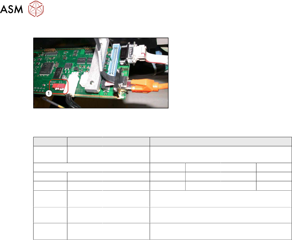
Coding the DIP Switch (6 Pin)
Fig.109: Setting the DIP switches
► Set the DIP switch (1) on the camera.
DIP switch S1 for SST25 and SST33
Switch Status Signal name Description
S1.1 OFF VCU_CODE OFF: normal operation
ON: Reset
Location 1 Location 2 Location 3 Location 4
S1.2 ON/OFF *) PORTAL_ID_0 OFF ON OFF ON
S1.3 ON/OFF *) GANTRY_ID_1 OFF OFF ON ON
S1.4 OFF SMD_LED OFF: standard LED
ON: SMD LED
S1.5 OFF CAN_H OFF: with CAN terminator
ON: without CAN terminator
S1.6 ON/OFF CAN_GROUP OFF: FC camera
ON: IC camera
4.3.1.2 Fitting the IC Camera Type 33
The camera is fixed at two spacer plates, which have already been screwed to the screw fixing
points on the machine base.
The procedure for fitting these spacer plates and for fixing the cameras is in principle the same at
all locations. Any differences are indicated in the following section.
► Before installation, make sure that the jumper setting for the camera to be fitted is correct (see
4.3.1.1
"Adjusting the Camera Jumper Setting" [}147]).
See also
2 4.3.1.2.2 "IC Camera Type 33: Fixing the Camera Module" [}152]
4 Appendix
4.3 Excerpt from the assembly instructions "SIPLACE X-Series S - stationary camera type
25/33" [00197397‑xx]
Assembly Instructions / Montageanleitung SIPLACE X-Series S 3D-Sensor 06/2020 149
Fitting the Spacer Plates
The spacer plates are fixed to the relevant screw fixing points in the machine base. Narrow spacer
plates are used at locations 2 and 3, while wide spacer plates are used at locations 1 and 4.
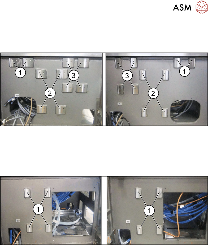
Screw fixing points at location 2 and 3
Fig.110: Screw fixing points at location 2 (left) and 3 (right)
1. Screw fixing points for the reject bin
2. Screw fixing points for the IC camera type 33
3. Screw fixing points for the IFC camera type 25
The screw fixing points at location 2 and 3 are mirrored. Use the left holes at location 2.
Screw fixing points at location 1 and 4
Fig.111: Screw fixing points at location 1 (left) and 4 (right)
1. Screw fixing points for the IC camera type 33
4 Appendix
4.3 Excerpt from the assembly instructions "SIPLACE X-Series S - stationary camera type
25/33" [00197397‑xx]
150 Assembly Instructions / Montageanleitung SIPLACE X-Series S 3D-Sensor 06/2020
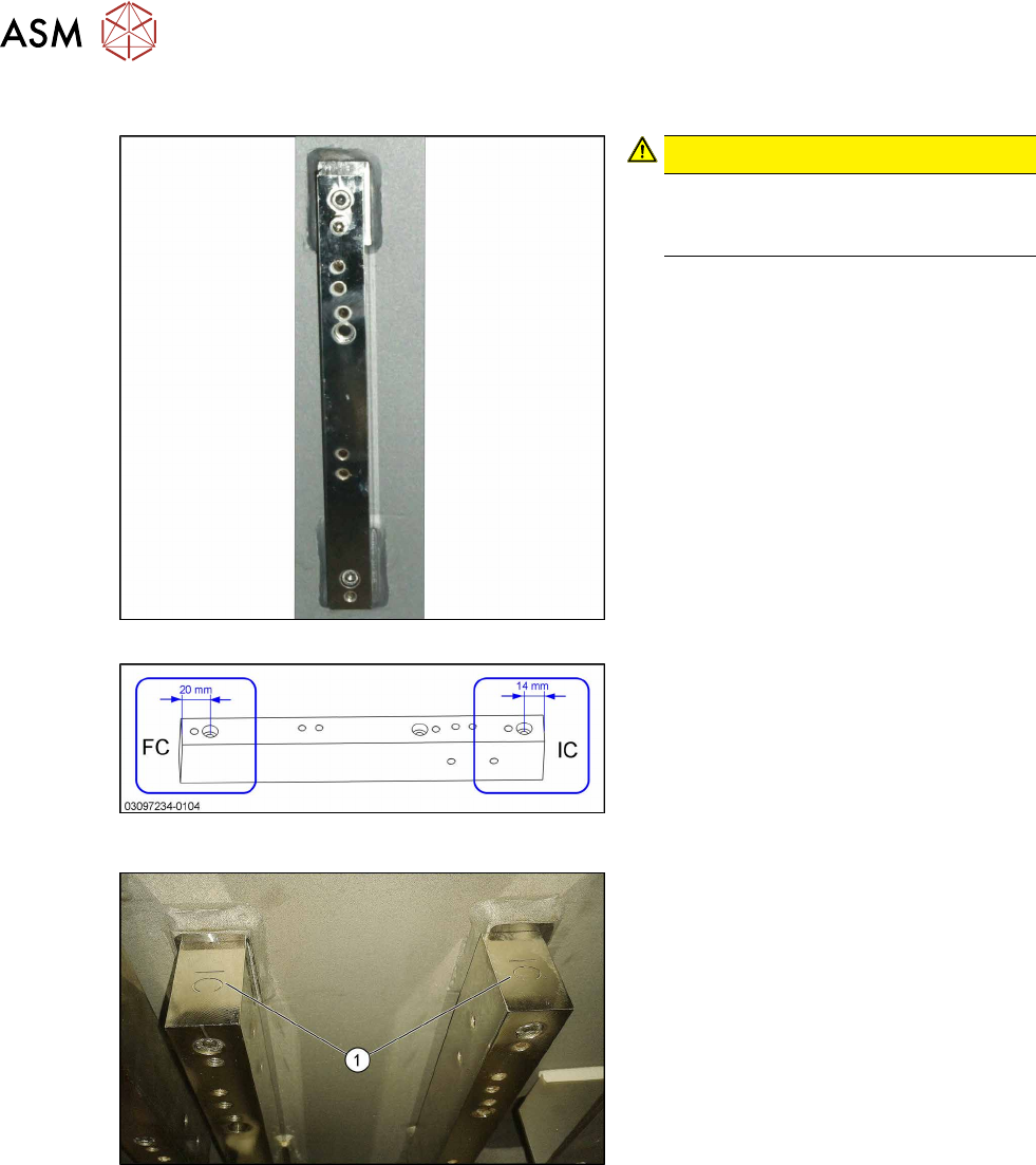
Spacer plates for locations 2 and 3
Fig.112: Narrow spacer plates for locations 2 and 3
Fig.113: Correct labeling of spacer plates
CAUTION!
Incorrect labeling
In a few cases, these spacer plates
are supplied with incorrect labeling.
.
► Compare your spacer plates with the
diagram.
If the label does not match the diagram,
correct the label.
– FC: This side must be on top for FC
cameras and Q10 magazines
(Smart Pin Support).
– IC: This side must be on top for IC
cameras.
Fig.114: IC top
IC and FC are marked on the top and bot-
tom of the spacer plates.
When fitting an IC camera, make sure that
the IC lettering (1)
faces upwards.