00197395-03_AI_3D_Sensor-Koplan_X-Serie_S_DE_EN.pdf - 第95页
2 Brief Description 2.1 Overview of Functions Assembly Instructions / Montageanleitung SIPLACE X-Series S 3D-Sensor 06/2020 95 2 Brief Description 2.1 Overview of Functions The coplanarity of a component is measured to p…

1 Introduction
1.4 Staff qualifications and training
94 Assembly Instructions / Montageanleitung SIPLACE X-Series S 3D-Sensor 06/2020
2 Brief Description
2.1 Overview of Functions
Assembly Instructions / Montageanleitung SIPLACE X-Series S 3D-Sensor 06/2020 95
2 Brief Description
2.1 Overview of Functions
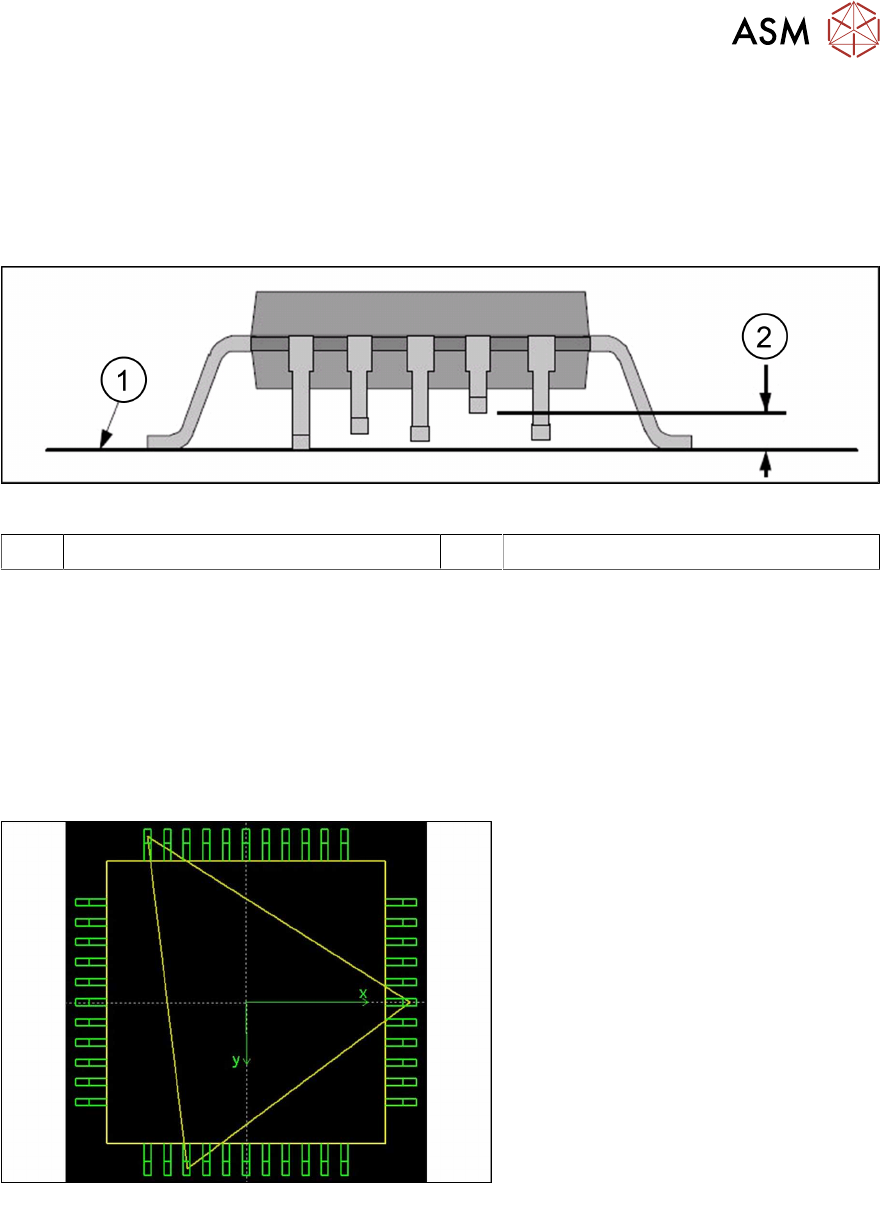
The coplanarity of a component is measured to prevent solder problems due to deformed (bent)
leads. Before placement, it is checked that all leads can reliably touch the solder paste.
Fig.7: Measuring the coplanarity of a component
1 Contact surface 2 Coplanarity deviation
The following steps are required to measure the coplanarity:
► Measuring the lead height (relative to the 3D sensor)
► Determining the contact surface (the three leads on which the component will rest when
placed onto the board).
► Determining the lead with the greatest distance to this contact surface and comparing this dis-
tance to the coplanarity threshold, which is generally somewhat less than the solder paste
thickness.
This measurement will then determine whether the component is to be placed or rejected.
Fig.8: Component contact surface
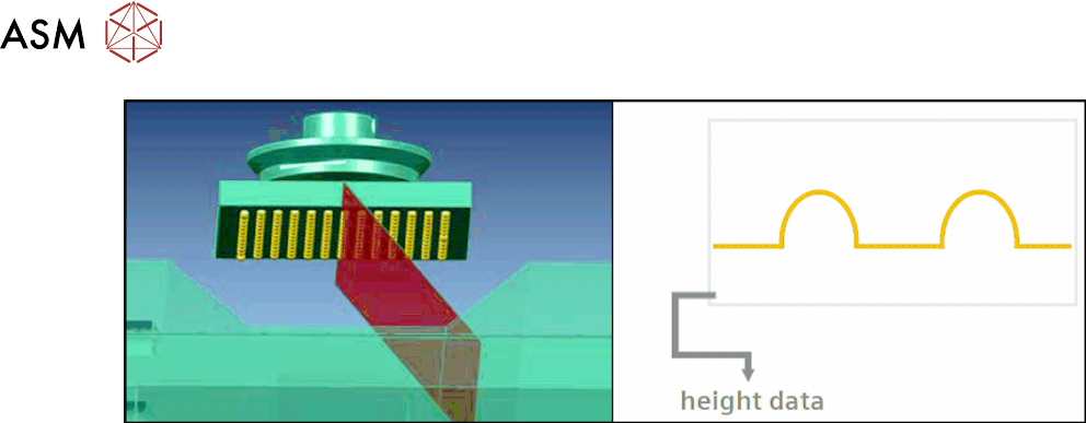
The 3D sensor operates according to the
laser triangulation principle. A laser
beam is projected onto the component
from a 45° angle. The laser beam profile
is then recorded by a camera.
2 Brief Description
2.2 Requirements/Restrictions
96 Assembly Instructions / Montageanleitung SIPLACE X-Series S 3D-Sensor 06/2020
Fig.9: Laser line profile
The component is moved over the 3D sensor. This produces multiple laser beam profiles which,
when placed in sequence, show the height of the component. This height image allows the lead
heights to be determined and the coplanarity value to then be calculated.
2.2 Requirements/Restrictions
The installation of the 3D coplanarity sensor is only possible at location 2 in SIPLACE X2 S, X3 S
and X4 S machines.
The 3D sensor can only be fitted at location 2 in place of the FC camera. If there is already an FC
camera fitted, this must be removed.
The 3D sensor can be operated with either the TwinHead or the CPP head. The CPP head is only
supported in its high installation position.