00197395-03_AI_3D_Sensor-Koplan_X-Serie_S_DE_EN.pdf - 第82页
82 Assembly Instructions / Montageanleitung SIPLACE X-Series S 3D-Sensor 06/2020 Contents: 3.10 Fitting the station computer (from Hxxxx) .. 115 3.11 Installing the station computer (up to Gxxxx) .. 116 3.12 Installi…

81Assembly Instructions / Montageanleitung SIPLACE X-Series S 3D-Sensor 06/2020
Contents:
Contents:
1 Introduction.. 83
1.1 Safety instructions.. 83
1.1.1 Conventions for the use of safety instructions and symbols.. 83
1.1.2 Safety instructions for the power supply (without SMPS).. 84
1.1.3 Safety instructions for the power supply (with SMPS).. 85
1.1.4 Safety instructions for work on the cutting device.. 86
1.1.5 Safety instructions for the gantry.. 87
1.1.6 Safety instructions on hazardous materials.. 87
1.1.7 Classification of the optical systems.. 87
1.1.7.1 Classification of the whole machine.. 87
1.1.7.2 Laser classification.. 87
1.1.7.3 Classification of the camera systems.. 87
1.1.8 Safety instructions for the sensor of the coplanarity module.. 88
1.2 Preparatory work..... 89
1.3 Other instructions.. 91
1.3.1 Environmentally-friendly disposal of materials and components.. 91
1.3.2 Use of original accessories and spare parts.. 91
1.3.3 ESD guidelines.. 91
1.3.3.1 What does ESD mean?.. 91
1.3.3.2 Important measures to protect against static charging.. 92
1.3.3.3 Handling ESD modules.. 92
1.3.3.4 Measurements and modifications to ESD modules.. 92
1.3.3.5 Dispatching ESD modules.. 92
1.3.4 Release History.. 93
1.4 Staff qualifications and training.. 93
2 Brief Description.. 95
2.1 Overview of Functions.. 95
2.2 Requirements/Restrictions.. 96
2.3 Scope of Delivery.. 97
2.3.1 Overview of Parts.. 98
2.4 Tools and Equipment Required.. 98
2.5 Required Working Time.. 98
3 Installation.. 99
3.1 Preparing the Workplace.. 99
3.2 Preparing the Installation of the IC Camera (Type 33).. 99
3.3 Fastening the 3D Coplanarity Module.. 101
3.4 Sticking the Laser Warning Labels Into Place.. 102
3.5 Removing the Station Computer.. 103
3.6 Running the cable for the coplanarity computer.. 103
3.7 Connecting the Cable to the (M)GCU.. 106
3.7.1 Overview of GCUs.. 108
3.7.2 Overview of MGCUs.. 110
3.8 Connecting the Cable to 3D Coplanarity Module.. 113
3.9 Installing the LAN card in the station computer (from Hxxxx).. 114

82 Assembly Instructions / Montageanleitung SIPLACE X-Series S 3D-Sensor 06/2020
Contents:
3.10 Fitting the station computer (from Hxxxx).. 115
3.11 Installing the station computer (up to Gxxxx).. 116
3.12 Installing the Coplanarity Computer.. 118
3.12.1 Preparing the Coplan Computer.. 118
3.12.2 Fixing the Coplan Computer and Routing the Cables.. 120
3.13 Completing the Mechanical Work.. 122
3.14 Installing station software 7xx on the coplanarity computer.. 123
3.15 Reconnecting the Station Computer.. 125
3.16 Configuring the LAN card in the station computer (from Hxxxx).. 125
3.17 Commissioning with SW 70x.. 126
3.17.1 Adapting the Configuration.. 126
3.17.2 Calibrating the Stationary Camera SST33.. 127
3.17.3 Calibrating the 3D Coplanarity Module.. 130
3.17.4 Performing the MFU.. 133
4 Appendix.. 137
4.1 Excerpts from the Service Manual.. 137
4.1.1 Replacing the waste tape slide.. 137
4.1.2 Vision LED driver VLT 33.. 138
4.1.3 Vision LED Controller VLC25/33 GigE DTC.. 139
4.2 Excerpt from the assembly instructions "SIPLACE X-Series S, SX-Series V3 station-
ary camera type 25/33 (GigE)" [00197710‑xx]..
140
4.2.1 Fitting the Camera.. 140
4.2.1.1 Adjusting the Camera Jumper Setting.. 141
4.2.1.2 Fitting the IC Camera Type 33.. 141
4.3 Excerpt from the assembly instructions "SIPLACE X-Series S - stationary camera
type 25/33" [00197397‑xx]..
146
4.3.1 Fitting the Camera.. 146
4.3.1.1 Adjusting the Camera Jumper Setting.. 147
4.3.1.2 Fitting the IC Camera Type 33.. 148
4.4 Circuit Diagrams.. 153
4.4.1 Circuit diagrams (up to Gxxxx).. 153
4.4.2 Circuit diagrams (from Hxxxx).. 155
1 Introduction
1.1 Safety instructions
Assembly Instructions / Montageanleitung SIPLACE X-Series S 3D-Sensor 06/2020 83
1 Introduction
This manual describes the installation of the 3D sensor (coplanarity) in SIPLACE® machines of
type X2 S, X3 S and X4 S, plus the installation of the software and the commissioning.
1.1 Safety instructions
DANGER
Nonobservance of these safety instructions may cause injury to personnel and dam-
age to the machine!
► Please observe the safety instructions in the user manual of the relevant machine
for all work!
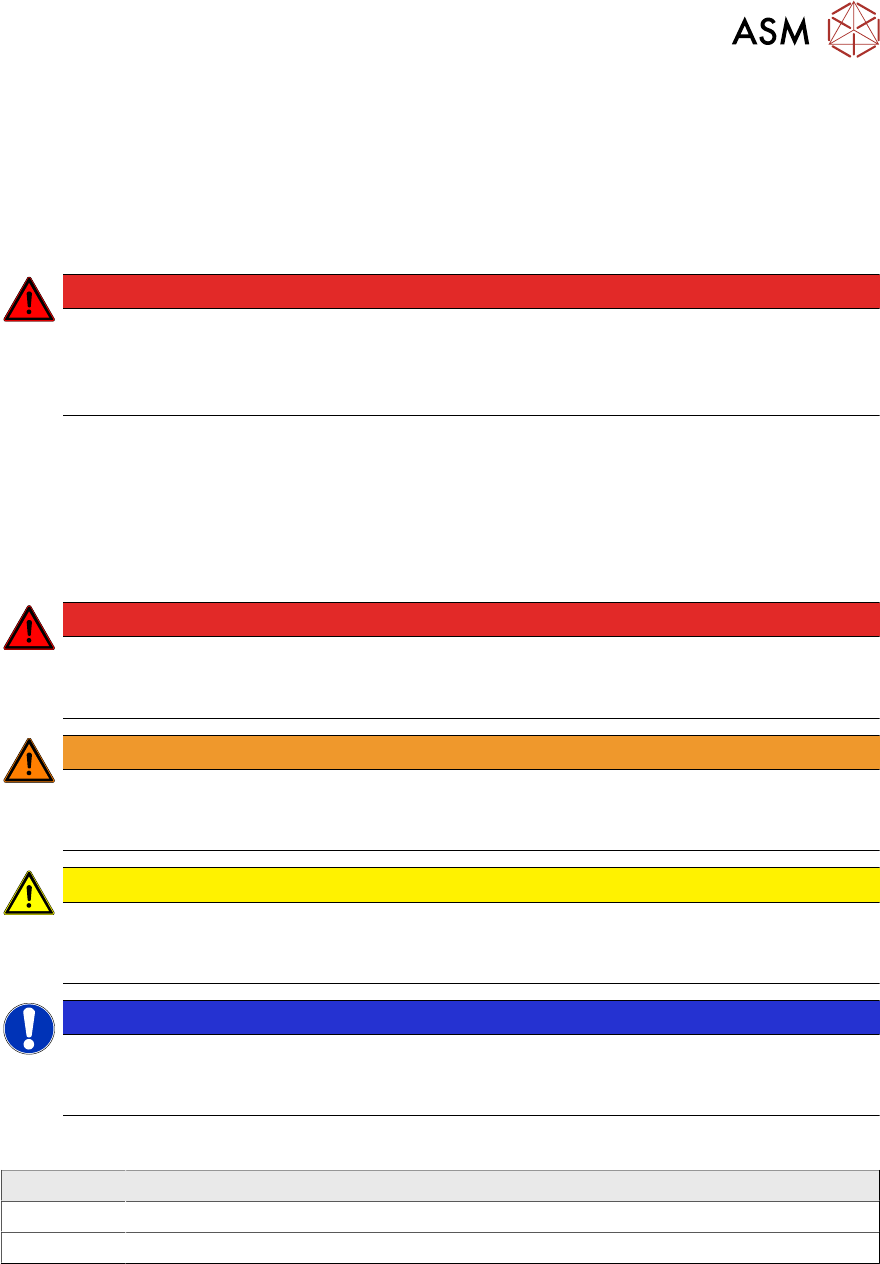
1.1.1 Conventions for the use of safety instructions and symbols
Safety instructions
This manual contains notes that must be observed to guarantee your personal safety and to avoid
damage to equipment. These notes are highlighted by warning triangles and are indicated as fol-
lows according to the level of risk:
DANGER
Definition
For the purposes of this manual, this indicates that fatal or severe injuries or considerable
damage to property will occur if this hazard warning is not observed.
WARNING
Definition
For the purposes of this manual, this indicates that fatal or severe injuries or considerable
damage to equipment may occur if these warning instructions are not followed.
CAUTION
Definition
For the purposes of this manual, this indicates that minor injuries or damage to property
may occur if this caution is not observed.
NOTICE
Definition
For the purposes of this manual, this note provides information about the product or indic-
ates a part of the manual that requires particular attention.
Symbols
Example Description
Next This typeface marks controls and interface elements in the software.
► This symbol indicates actions that have to be performed by the operator.