00197395-03_AI_3D_Sensor-Koplan_X-Serie_S_DE_EN.pdf - 第134页
3 Installation 3.17 Commissioning with SW 70x 134 Assembly Instructions / Montageanleitung SIPLACE X-Series S 3D-Sensor 06/2020 Fig.84: Placement sections view ► Click on the following buttons in se- quence Placement se…
3 Installation
3.17 Commissioning with SW 70x
Assembly Instructions / Montageanleitung SIPLACE X-Series S 3D-Sensor 06/2020 133
3.17.4 Performing the MFU
Perform a 3D coplanarity MFU with the FCCS tray.
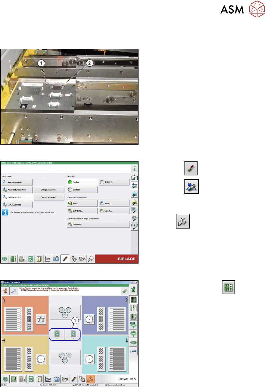
Fig.81: Input conveyor with FCCS tray
► Replace the nozzles on the TwinHead
for nozzles of type 519.
► Place the FCCS tray (1) on the input
conveyor of the machine.
► Place the MFU tool into the marked
groove (2)
.
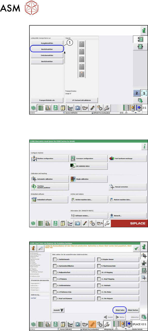
Fig.82: Select operator level
► Select the button.
► Select the button.
► Switch over to the operator level Ma-
chine service.
ð The button will be shown.
Fig.83: View: setup locations
► Switch over to the menu .
► Select the relevant location(1).
ð The placement section view will be
opened.
3 Installation
3.17 Commissioning with SW 70x
134 Assembly Instructions / Montageanleitung SIPLACE X-Series S 3D-Sensor 06/2020
Fig.84: Placement sections view
► Click on the following buttons in se-
quence Placement section, Interme-
diate section and Placement sec-
tion(1).
ð The board moves into placement
section 2.
Up to SW 711.x
Fig.85: Automatic calibration
► Select the Automatic calibration but-
ton.
ð The calibration selection view will be
opened.
Fig.86: Calibration step "coplanarity sensor" option
► Go to the Automatic calibration menu
and select the Load script
button.
ð The Load calibration scripting file
view will be opened.
3 Installation
3.17 Commissioning with SW 70x
Assembly Instructions / Montageanleitung SIPLACE X-Series S 3D-Sensor 06/2020 135
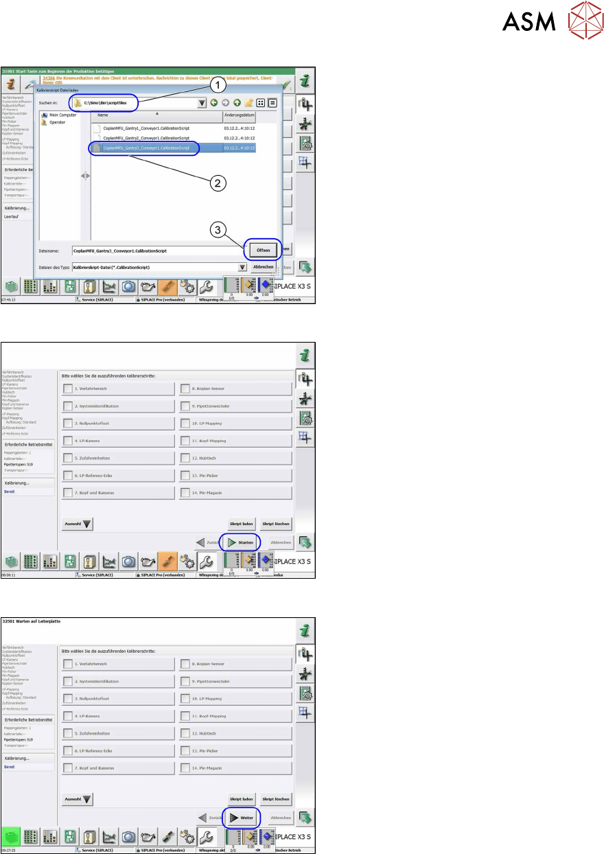
Fig.87: Loading the calibration script file
► Open the
C:\Sirio\Bin\scriptfiles
(1) folder.
► Select the relevant file for the gantry
(2)
.
► Select the Open(3) button.
ð The calibration selection view will be
opened.
Fig.88: Calibration steps options
If there are already nozzles of type 519 on
the TwinHead, the Start
button will be act-
ive.
► Select the Start button to begin cali-
bration.
Fig.89: Calibration steps options
If the right nozzles are not on the head, the
Next
button will be active .
► Choose the Next button.
ð The dialog for correcting the nozzle
type will appear.